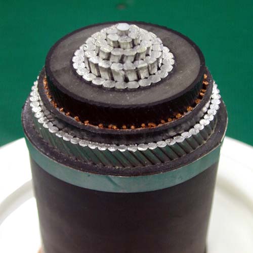
600V~25kV Cross-Linked Polyethylene Insulated, steel wires armor and Low-Smoke and Halogen-Free (LSHF) Compound Jacketed Power Cables. It is used at wiring for power distribution system. The power cables shall comply with the standard of IEC 60502. Features Construction:(1) Conductor: untinned soft annealed stranded or solid copper wires (2) Conductor screen (voltage >2001V) (3) Insulation: XLPE. (4) Insulation screen (voltage > 2001V) (5) Copper tape shielding (voltage > 2001V) (6) Two or more cores are twisted together,cable core covered with proper separator (7) Inner Sheath: LSHF (8) Steel wires armor (9) Sheath: LSHF Introduction: 600V~25kV Cross-Linked Polyethylene Insulated, steel wires armor, Low-Smoke and Halogen-Free (LSHF) Compound Jacketed Power Cables (CL-SWA). It has following characteristics: (1) Low toxicity index; per NES 713; toxicity index <=5 (2) Don’t produce halogen gas; per IEC 60754-1; Amount of HCL gas <=0.5% (3) Low smoke; LSHF compound per ASTM E662 smoke density test; Ds<=250,VOF4<=100 (4) Excellent flame resistance; per ASTM D2863 oxygen index; OI >=30; per IEEE 383 vertical open tray flame test; passed. The Low-Smoke and Halogen-Free (LSHF) wire and cable could minimize the lowest damage in case of fire. Therefore, the public areas, such as subway, tunnel, railway, public building, substreet, ships, power stations, school, hospital, and rapid transit system in more suitable to install the LSHF cable to secure the human lives and properties. Specifications 600V XLPE insulated, steel wire armor, LSHF sheathed cables 1C (CL-SWA) Conductor Thickness of insulation mm Approx.Overall Diameter mm Approx. Weight Kg/km Normative Cross Area mm2 Number/ Diameter of Wires No./mm Outer DiameterApprox. mm - 1/1.0 1.0 0.7 9.9 160 - 1/1.2 1.2 0.7 10.1 170 - 1/1.6 1.6 0.7 10.5 190 - 1/2.0 2.0 0.7 10.9 215 - 1/2.6 2.6 0.7 11.5 250 - 1/3.2 3.2 0.7 12.1 290 2 7/0.6 1.8 0.7 10.7 195 1.25 7/0.45 1.35 0.7 10.4 165 3.5 7/0.8 2.4 0.7 11.3 225 5.5 7/1.0 3.0 0.7 11.9 265 8 7/1.2 3.4 0.7 12.3 300 14 7/1.6 4.4 0.7 13.3 385 22 7/2.0 5.5 0.7 14.4 490 30 7/2.3 6.4 0.9 15.9 605 38 7/2.6 7.3 0.9 16.8 715 50 19/1.8 8.4 1.0 18.2 860 60 19/2.0 9.3 1.0 19.1 995 80 19/2.3 10.7 1.1 22.5 1495 100 19/2.6 12.0 1.1 23.8 1755 125 19/2.9 13.5 1.2 25.5 2075 150 37/2.3 14.7 1.4 27.3 2435 200 37/2.6 17.0 1.6 30.2 2990 250 61/2.3 19.0 1.7 33.6 3870 325 61/2.6 21.7 1.8 36.8 4735 400 61/2.9 24.1 2.0 40.0 5690 500 61/3.2 26.9 2.2 41.1 6740 600V XLPE insulated, steel wire armor, LSHF sheathed cables 2C (CL-SWA) Conductor Thickness of insulation mm Approx.Overall Diameter mm Approx. Weight Kg/km Normative Cross Area mm2 Number/ Diameter of Wires No./mm Outer DiameterApprox. mm - 1/1.0 1.0 0.7 13.0 265 - 1/1.2 1.2 0.7 13.3 281 - 1/1.6 1.6 0.7 14.1 325 - 1/2.0 2.0 0.7 15.0 380 - 1/2.6 2.6 0.7 16.4 470 - 1/3.2 3.2 0.7 17.6 564 2 7/0.6 1.8 0.7 14.7 350 1.25 7/0.45 1.35 0.7 13.9 295 3.5 7/0.8 2.4 0.7 16.0 420 5.5 7/1.0 3.0 0.7 17.1 500 8 7/1.2 3.4 0.7 18.0 575 14 7/1.6 4.4 0.7 20.1 770 22 7/2.0 5.5 0.7 24.0 1295 30 7/2.3 6.4 0.9 26.7 1590 38 7/2.6 7.3 0.9 29.7 1945 50 19/1.8 8.4 1.0 31.6 2255 60 19/2.0 9.3 1.0 34.6 2830 80 19/2.3 10.7 1.1 38.0 3435 100 19/2.6 12.0 1.1 41.1 4070 125 19/2.9 13.5 1.2 46.0 5220 150 37/2.3 14.7 1.4 49.3 6070 200 37/2.6 17.0 1.6 55.6 7455 250 61/2.3 19.0 1.7 60.6 9035 325 61/2.6 21.7 1.8 67.4 10885 400 61/2.9 24.1 2.0 73.6 14060 500 61/3.2 26.9 2.2 81.3 15660 600V XLPE insulated, steel wire armor, LSHF sheathed cables 3C (CL-SWA) Conductor Thickness of insulation mm Approx.Overall Diameter mm Approx. Weight Kg/km Normative Cross Area mm2 Number/ Diameter of Wires No./mm Outer DiameterApprox. mm - 1/1.0 1.0 0.7 13.4 285 - 1/1.2 1.2 0.7 13.8 310 - 1/1.6 1.6 0.7 14.9 370 - 1/2.0 2.0 0.7 15.7 445 - 1/2.6 2.6 0.7 17.0 545 - 1/3.2 3.2 0.7 18.3 665 2 7/0.6 1.8 0.7 15.3 390 1.25 7/0.45 1.35 0.7 14.3 325 3.5 7/0.8 2.4 0.7 16.6 480 5.5 7/1.0 3.0 0.7 17.9 580 8 7/1.2 3.4 0.7 18.7 685 14 7/1.6 4.4 0.7 22.7 1200 22 7/2.0 5.5 0.7 25.1 1555 30 7/2.3 6.4 0.9 28.1 1945 38 7/2.6 7.3 0.9 30.2 2295 50 19/1.8 8.4 1.0 34.5 3040 60 19/2.0 9.3 1.0 36.7 3500 80 19/2.3 10.7 1.1 40.5 4325 100 19/2.6 12.0 1.1 43.6 5190 125 19/2.9 13.5 1.2 48.7 6600 150 37/2.3 14.7 1.4 52.7 7720 200 37/2.6 17.0 1.6 59.4 9610 250 61/2.3 19.0 1.7 64.5 11725 325 61/2.6 21.7 1.8 71.8 14510 400 61/2.9 24.1 2.0 79.9 18420 500 61/3.2 26.9 2.2 87.9 21930 600V XLPE insulated, steel wire armor, LSHF sheathed cables 4C (CL-SWA) Conductor Thickness of insulation mm Approx.Overall Diameter mm Approx. Weight Kg/km Normative Cross Area mm2 Number/ Diameter of Wires No./mm Outer DiameterApprox. mm - 1/1.0 1.0 0.7 14.1 320 - 1/1.2 1.2 0.7 14.7 355 - 1/1.6 1.6 0.7 15.7 425 - 1/2.0 2.0 0.7 16.7 500 - 1/2.6 2.6 0.7 18.1 635 - 1/3.2 3.2 0.7 19.6 785 2 7/0.6 1.8 0.7 16.2 405 1.25 7/0.45 1.35 0.7 15.1 365 3.5 7/0.8 2.4 0.7 17.4 555 5.5 7/1.0 3.0 0.7 19.1 680 8 7/1.2 3.4 0.7 20.3 815 14 7/1.6 4.4 0.7 24.3 1420 22 7/2.0 5.5 0.7 27.1 1890 30 7/2.3 6.4 0.9 30.5 2370 38 7/2.6 7.3 0.9 33.8 3055 50 19/1.8 8.4 1.0 37.3 3705 60 19/2.0 9.3 1.0 39.9 5395 80 19/2.3 10.7 1.1 45.3 5825 100 19/2.6 12.0 1.1 48.8 6895 125 19/2.9 13.5 1.2 53.5 8195 150 37/2.3 14.7 1.4 57.8 9690 200 37/2.6 17.0 1.6 64.9 12015 250 61/2.3 19.0 1.7 70.8 14780 325 61/2.6 21.7 1.8 80.5 19260 400 61/2.9 24.1 2.0 87.9 23195 500 61/3.2 26.9 2.2 96.6 27620
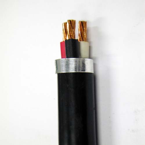
600V~25kV Cross-Linked Polyethylene Insulated and Low-Smoke and Halogen-Free (LSHF) Compound Jacketed Power and Control Cables. It is used at wiring for power and control circuit of distribution system. The control cables shall comply with the standard of IEC 60502. Features Construction:(1) Conductor: untinned soft annealed stranded or solid copper wires (2) Conductor screen (voltage >2001V) (3) Insulation: XLPE. (4) Insulation screen (voltage > 2001V) (5) Copper tape shielding (voltage > 2001V) (6) Two or more cores are twisted together,cable core covered with proper separator (7) Sheath: LSHF Introduction: 600V~25kV Cross-Linked Polyethylene Insulated and Low-Smoke and Halogen-Free (LSHF) Compound Jacketed Power and Control Cables (CL). It has following characteristics: (1) Low toxicity index; per NES 713; toxicity index <=5 (2) Don’t produce halogen gas; per IEC 60754-1; Amount of HCL gas <=0.5% (3) Low smoke; LSHF compound per ASTM E662 smoke density test; Ds<=250,VOF4<=100 (4) Excellent flame resistance; per ASTM D2863 oxygen index; OI >=30; per IEEE 383 vertical open tray flame test; passed. The Low-Smoke and Halogen-Free (LSHF) wire and cable could minimize the lowest damage in case of fire. Therefore, the public areas, such as subway, tunnel, railway, public building, substreet, ships, power stations, school, hospital, and rapid transit system in more suitable to install the LSHF cable to secure the human lives and properties. Specifications 600V XLPE Insulated and LSHF sheathed cables 1C (CL) Conductor Thickness of insulation mm Approx.Overall Diameter mm Approx.Weight Kg/km Normative Cross Area mm2 Number/ Diameter of Wires No./mm Outer DiameterApprox. mm 1.25 7/0.45 1.35 0.7 6.2 45 2.0 7/0.6 1.8 0.7 6.6 55 3.5 7/0.8 2.4 0.7 7.2 75 5.5 7/1.0 3.0 0.7 7.8 100 8 7/1.2 3.4 0.7 8.2 125 14 7/1.6 4.4 0.7 9.2 190 22 7/2.0 5.5 0.7 10.3 275 30 7/2.3 6.4 0.9 11.6 355 38 7/2.6 7.3 0.9 12.5 435 50 19/1.8 8.4 1.0 13.9 550 60 19/2.0 9.3 1.0 14.8 665 80 19/2.3 10.7 1.1 16.5 860 100 19/2.6 12.0 1.1 17.9 1080 125 19/2.9 13.5 1.2 19.7 1330 150 37/2.3 14.7 1.4 21.5 1625 200 37/2.6 17.0 1.6 24.3 2060 250 61/2.3 19.0 1.7 26.7 2625 325 61/2.6 21.7 1.8 29.9 3335 400 61/2.9 24.1 2.0 32.9 4130 500 61/3.2 26.9 2.2 36.3 5005 600V XLPE Insulated and LSHF sheathed cables 2C (CL) Conductor Thickness of insulation mm Approx.Overall Diameter mm Approx. Weight Kg/km Normative Cross Area mm2 Number/ Diameter of Wires No./mm Outer DiameterApprox. mm 1.25 7/0.45 1.35 0.7 10.4 110 2.0 7/0.6 1.8 0.7 11.3 135 3.5 7/0.8 2.4 0.7 12.5 180 5.5 7/1.0 3.0 0.7 13.7 235 8 7/1.2 3.4 0.7 14.5 295 14 7/1.6 4.4 0.7 16.5 440 22 7/2.0 5.5 0.7 18.7 625 30 7/2.3 6.4 0.9 21.3 810 38 7/2.6 7.3 0.9 24.1 1025 50 19/1.8 8.4 1.0 25.8 1265 60 19/2.0 9.3 1.0 27.7 1520 80 19/2.3 10.7 1.1 31.1 1965 100 19/2.6 12.0 1.1 34.0 2470 125 19/2.9 13.5 1.2 37.6 3040 150 37/2.3 14.7 1.4 41.0 3705 200 37/2.6 17.0 1.6 47.0 4735 250 61/2.3 19.0 1.7 51.7 6010 325 61/2.6 21.7 1.8 58.2 7470 400 61/2.9 24.1 2.0 64.1 9445 500 61/3.2 26.9 2.2 71.0 11485 600V XLPE Insulated and LSHF sheathed cables 3C (CL) Conductor Thickness of insulation mm Approx.Overall Diameter mm Approx. Weight Kg/km Normative Cross Area mm2 Number/ Diameter of Wires No./mm Outer DiameterApprox. mm 1.25 7/0.45 1.35 0.7 10.9 110 2.0 7/0.6 1.8 0.7 11.8 135 3.5 7/0.8 2.4 0.7 13.1 180 5.5 7/1.0 3.0 0.7 14.4 235 8 7/1.2 3.4 0.7 15.3 295 14 7/1.6 4.4 0.7 17.4 440 22 7/2.0 5.5 0.7 19.8 625 30 7/2.3 6.4 0.9 22.6 810 38 7/2.6 7.3 24.5 24.5 1025 50 19/1.8 8.4 1.0 27.4 1265 60 19/2.0 9.3 1.0 29.6 1520 80 19/2.3 10.7 1.1 33.2 1965 100 19/2.6 12.0 1.1 36.3 2470 125 19/2.9 13.5 1.2 40.3 3040 150 37/2.3 14.7 1.4 43.9 3705 200 37/2.6 17.0 1.6 50.4 4735 250 61/2.3 19.0 1.7 55.6 6010 325 61/2.6 21.7 1.8 62.4 7470 400 61/2.9 24.1 2.0 68.9 9445 500 61/3.2 26.9 2.2 76.3 11485 600V XLPE Insulated and LSHF sheathed cables 4C (CL) Conductor Thickness of insulation mm Approx.Overall Diameter mm Approx. Weight Kg/km Normative Cross Area mm2 Number/ Diameter of Wires No./mm Outer DiameterApprox. mm 1.25 7/0.45 1.35 0.7 11.7 150 2.0 7/0.6 1.8 0.7 12.7 160 3.5 7/0.8 2.4 0.7 14.2 275 5.5 7/1.0 3.0 0.7 15.6 370 8 7/1.2 3.4 0.7 16.5 480 14 7/1.6 4.4 0.7 19.0 750 22 7/2.0 5.5 0.7 21.6 1010 30 7/2.3 6.4 0.9 24.8 1430 38 7/2.6 7.3 24.5 26.6 1780 50 19/1.8 8.4 1.0 30.1 2280 60 19/2.0 9.3 1.0 32.4 2760 80 19/2.3 10.7 1.1 36.6 3600 100 19/2.6 12.0 1.1 40.1 4535 125 19/2.9 13.5 1.2 44.5 5600 150 37/2.3 14.7 1.4 48.5 6850 200 37/2.6 17.0 1.6 55.5 8745 250 61/2.3 19.0 1.7 61.3 11150 325 61/2.6 21.7 1.8 69.0 12400 400 61/2.9 24.1 2.0 76.3 17600 500 61/3.2 26.9 2.2 84.5 21380 22KV XLPE insulated and LSHF sheathed cables 1C (CL) Conductor Thickness of insulation mm Approx.Overall Diameter mm Approx. Weight Kg/km Normative Cross Area mm2 Number/ Diameter of Wires No./mm Outer DiameterApprox. mm 38 7/2.6 7.3 5.5 25.8 882 60 19/2.0 9.3 5.5 28.7 1183 80 19/2.3 10.7 5.5 29.5 1382 100 19/2.6 12.0 5.5 30.9 1635 125 19/2.9 13.5 5.5 33.3 1960 200 37/2.6 17.0 5.5 37.2 2758 250 61/2.3 19.0 5.5 39.2 3347 325 61/2.6 21.7 5.5 42.6 4149 400 61/2.9 24.1 5.5 44.3 4911 22KV XLPE insulated and LSHF sheathed cables 3C (CL) Conductor Thickness of insulation mm Approx. Overall Diameter mm Approx. Weight Kg/km Normative Cross Area mm2 Number/ Diameter of Wires No./mm Outer Diameter Approx. mm 38 7/2.6 7.3 5.5 53.9 3254 60 19/2.0 9.3 5.5 60.2 4195 80 19/2.3 10.7 5.5 62.0 4860 100 19/2.6 12.0 5.5 64.7 5659 125 19/2.9 13.5 5.5 70.2 6589 200 37/2.6 17.0 5.5 78.4 9458 250 61/2.3 19.0 5.5 83.1 11459 325 61/2.6 21.7 5.5 90.4 14125
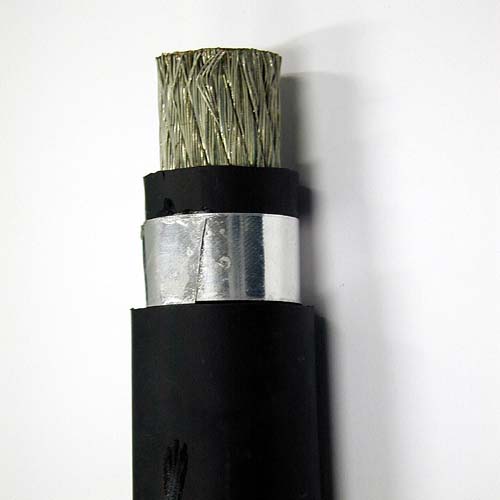
600V Second Type EPR (Ethylene Propylene Rubber) Insulated Neoprene Sheathed Flexible Cables (2PNCT). It shall comply with the standard of CNS 10741. Features Construction:(1) Conductor: tinned soft annealed stranded flexible copper wires (2) Insulation: EPR (3) Two or more cores are twisted together,cable core covered with proper separator (4) Sheath: Neoprene Introduction: The 2PNCT portable Cable with flexible conductor is used for Electric Machinery and Apparatus. The EPR insulated Neoprene (Polyvinyl Chloride) sheathed portable cable has excellent flexibility. It can withstand impact, bending, abrasion, elongation etc.. It has excellent oil-resistant and chemical-resistant properties. It has excellent heat-resistant, weatherproof properties. Specifications 600V 2PNCT SINGLE CORE CABLE Refer to CNS 10741 Conductor Thickness of insulation mm Approx.Overall Diameter mm Approx.Weight Kg/km StandardLength M Normative Cross Area mm2 Number/ Diameter of Wires No./mm Outer DiameterApprox. mm 0.75 30/0.18 1.1 0.8 5.8 48 200 1.25 50/0.18 1.5 0.8 6.2 60 200 2.0 37/0.26 1.8 0.8 6.5 70 200 3.5 45/0.32 2.5 0.8 7.4 95 200 5.5 70/0.32 3.1 1.0 8.4 130 200 8 50/0.45 3.7 1.0 9.2 165 200 14 88/0.45 4.9 1.0 11.0 240 200 22 7/20/0.45 7.0 1.2 13.5 375 200 30 7/27/0.45 8.1 1.2 15.0 470 200 38 7/34/0.45 9.1 1.2 16.0 570 200 50 19/16/0.45 10.4 1.5 18.0 720 200 60 19/20/0.45 11.6 1.5 19.5 870 200 80 19/27/0.45 13.5 2.0 23 1180 200 100 19/34/0.45 15.2 2.0 25 1430 200 600V 2PNCT TWO CORE CABLE Refer to CNS 10741 Conductor Thickness of insulation mm Approx.Overall Diameter mm Approx.Weight Kg/km StandardLength M Normative Cross Area mm2 Number/ Diameter of Wires No./mm Outer DiameterApprox. mm 0.75 30/0.18 1.1 0.8 9.0 115 200 1.25 50/0.18 1.5 0.8 9.8 140 200 2.0 37/0.26 1.8 0.8 11.0 175 200 3.5 45/0.32 2.5 0.8 12.5 245 200 5.5 70/0.32 3.1 1.0 14.5 350 200 8 50/0.45 3.7 1.0 16.0 435 200 14 88/0.45 4.9 1.0 18.5 640 200 22 7/20/0.45 7.0 1.2 25 1070 200 30 7/27/0.45 8.1 1.2 27 1340 200 38 7/34/0.45 9.1 1.2 30 1630 200 50 19/16/0.45 10.4 1.5 34 2100 200 60 19/20/0.45 11.6 1.5 37 2520 200 80 19/27/0.45 13.5 2.0 43 3470 200 100 19/34/0.45 15.2 2.0 47 4200 200 600V 2PNCT THREE CORE CABLE Refer to CNS 10741 Conductor Thickness of insulation mm Approx. Overall Diameter mm Approx. Weight Kg/km Standard Length M Normative Cross Area mm2 Number/ Diameter of Wires No./mm Outer Diameter Approx. mm 0.75 30/0.18 1.1 0.8 10.5 160 200 1.25 50/0.18 1.5 0.8 11.5 195 200 2.0 37/0.26 1.8 0.8 12.5 245 200 3.5 45/0.32 2.5 0.8 14.5 355 200 5.5 70/0.32 3.1 1.0 17.0 515 200 8 50/0.45 3.7 1.0 18.5 655 200 14 88/0.45 4.9 1.0 22 1000 200 22 7/20/0.45 7.0 1.2 29 1670 200 30 7/27/0.45 8.1 1.2 32 2100 200 38 7/34/0.45 9.1 1.2 35 2550 200 50 19/16/0.45 10.4 1.5 40 3320 200 60 19/20/0.45 11.6 1.5 44 4020 200 80 19/27/0.45 13.5 2.0 51 5500 200 100 19/34/0.45 15.2 2.0 56 6720 200 600V 2PNCT FOUR CORE CABLE Refer to CNS 10741 Conductor Thickness of insulation mm Approx.Overall Diameter mm Approx.Weight Kg/km StandardLength M Normative Cross Area mm2 Number/ Diameter of Wires No./mm Outer DiameterApprox. mm 0.75 30/0.18 1.1 0.8 9.4 130 200 1.25 50/0.18 1.5 0.8 10.5 175 200 2.0 37/0.26 1.8 0.8 11.5 200 200 3.5 45/0.32 2.5 0.8 13.0 290 200 5.5 70/0.32 3.1 1.0 15.5 415 200 8 50/0.45 3.7 1.0 17.0 525 200 14 88/0.45 4.9 1.0 20 795 200 22 7/20/0.45 7.0 1.2 27 1330 200 30 7/27/0.45 8.1 1.2 29 1670 200 38 7/34/0.45 9.1 1.2 32 2020 200 50 19/16/0.45 10.4 1.5 36 2620 200 60 19/20/0.45 11.6 1.5 39 3150 200 80 19/27/0.45 13.5 2.0 46 4320 200 100 19/34/0.45 15.2 2.0 50 5270 200
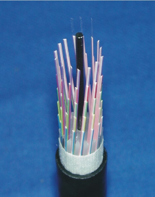
The optical cable is made of single mode multifiber ribbons that gathered in PE slotted spacer, and sheathed with laminated aluminum sheath.Slotted Ribbon Single mode Optical Cable (SR-SM Optical Cable) Application: 1.The SR-SM optical cables are suitable for long-haul, urban junction and subscriber loop communication. 2.The transmission wavelengths are 1310nm and 1550nm for G.652 optical cable. Structure: 1.Ribbon tape Color code: 4-fiber ribbon color code Fiber No. Ribbon No. Fiber color 1 2 3 4 1 B W or N W or N P 2 Y W or N W or N P 3 G W or N W or N P 4 R W or N W or N P 5 V W or N W or N P 8-fiber ribbon color code Fiber No. Ribbon No. Fiber color 1 2 3 4 5 6 7 8 1 B W W P Y W W P 2 G W W P R W W P 3 V W W P B W W W 4 Y W W W G W W W 5 R W W W V W W W 6 B W W Aq Y W W Aq 7 G W W Aq R W W Aq 8 V W W Aq B W W Br 9 Y W W Br G W W Br 10 R W W Br V W W Br B: Blue Y: Yellow G: Green R: Red V: Violet W: White Br: Brown Aq: Aqua P: Pink N: Natural 2. Basic cable structure 2.1 Single slotted spacer 2.2 Multiple slotted spacer 300C SSR-SM Optical Cable 600C BSR-SM Optical Cable Specification: 1.Dimension: (Only for reference) 1.1.Slotted spacer Item Specification Fiber count 4 ~ 100 4 ~ 100 200 300 400 600 200~600 Fiber in ribbon 4 4 4 4 8 8 4 Slotted Spacer count 1 1 1 1 1 1 2 ~ 6 Grooves in spacer 6 5 10 15 8 8 5 Type of spacer A C C C C C B Nominal outer diameter of spacer 9.4 9 13 15 18 18 8.5 1.2.Optical cable Fiber count Structure Overall diameter (mm) Approximate weight (Kg/Km) 4 ~ 100 ASR-LAP-SM 15 210 SSR-LAP-SM 14 150 200 SSR-LAP-SM 18 250 300 SSR-LAP-SM 21 330 400 SSR-LAP-SM 23 480 600 SSR-LAP-SM 23 540 200 ~ 600 BSR-LAP-SM 34 950 2.Optical properties Item Specification Attenuation (Long haul or junction) @1310nm < 0.4 dB/Km @1550nm < 0.3 dB/Km Attenuation (Subscriber loop) @1310nm < 0.5 dB/Km @1550nm < 0.35 dB/Km Attenuation Uniformity@1550nm < 0.1 dB Dispersion @1310 nm < 3.09 ps/km-nm @1550 nm < 18.21 ps/km-nm Zero dispersion wavelength (So) 1300 ~ 1322 nm Slope @So < 0.093 ps/km-nm2 Cabled cut-off wavelength @1310nm < 1270 nm Mode Field Diameter @1310nm 9.2 ± 0.5 mm Cable ordering code: Ordering code Description 0.4dB 100C ASR-LAP-SM 100-fiber slotted ribbon SM optical cable with LAP outer sheath, duct type 0.5dB 300C SSR-LAP-SM 300-fiber single slotted spacer ribbon SM optical cable with LAP outer sheath, duct type 0.5dB 600C BSR-LAP-SM 600-fiber multiple slotted spacer ribbon SM optical cable with LAP outer sheath, duct type 0.4dB 100C SSR-FR-LAP-SM 100-fiber single slotted spacer ribbon SM optical cable with flame retardant LAP outer sheath, indoor duct type ASR: A type Slotted Ribbon, spacer with 6 grooves BSR: B type Slotted Ribbon, spacer with 5 grooves SSR: Single Slotted Ribbon SM: Single Mode LAP: Laminated Aluminum PE sheath FR: Flame Retardant
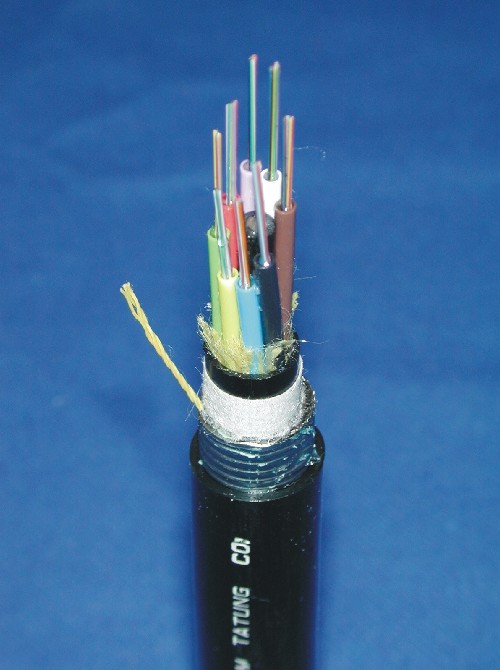
The jelly-filled loose tube single-mode(SM) optical cable is structured with the silica SM fibers, and the cable is filled with jelly.Loose Tube Jelly-filled Single mode Optical Cable (BJF-SM Optical Cable) Application: 1.The BJF-SM optical cables are suitable for long-haul and urban junction communication. 2.The transmission wavelengths are 1310nm and 1550nm for G.652 optical cable, 1530nm to 1625nm for G.655 NZD optical cable and broadband (1260nm to 1625nm) for G.652D. Structure: 1.Standard loose tube Basically, 6-fiber loose tube is applied in optical cable with optical fiber under 48C, 12-fiber loose tube is applied in optical cable with optical fiber above 48C. 6-fiber loose tube 12-fiber loose tube Color code: No. 1 2 3 4 5 6 Color Blue Yellow Green Red Violet White No. 7 8 9 10 11 12 Color Brown Black Aqua Orange Pink Gray 2.Basic cable structure 72C BJF-LAP-SM Optical cable 96C BJF-LSP-SM Optical cable 216C BJF-LAP-SS-SM Optical cable 96C BJF-NM-SM Optical cable Specification: 1.Dimensions: (Only for reference) 1.1.Loose tube Item Specification Fiber count 6 ~ 216 Fibers in loose tube 6 12 Nominal inner/outer diameter of loose tube 1.6/2.6 mm 2.0/3.0 mm 1.2.Optical cable Fiber count Structure Overall diameter (mm) Approximate weight (Kg/Km) 6 ~ 36 / 72 BJF-NM-SM 14.5 / 17.5 220 BJF-LAP-SM 14.8 / 17 220 BJF-LSP-SM 15.4 / 17.6 330 BJF-LAP-SS-SM 24.2´14.8 / 27.1´17 (a ´ b) 350 / 390 48 / 96 BJF-NM-SM 16.5 / 17.5 200 / 230 BJF-LAP-SM 16.3 / 20.5 330 BJF-LSP-SM 17 / 21.1 400 BJF-LAP-SS-SM 25.7´16.3 / 30.5´20.5 (a ´ b) 380 / 430 108 ~ 144 BJF-NM-SM 20.5 330 BJF-LAP-SM 23.1 350 BJF-LSP-SM 23.7 530 BJF-LAP-SS-SM 33.1´23.1 (a ´ b) 630 156 ~ 216 BJF-NM-SM 20.5 350 BJF-LAP-SM 23.1 430 BJF-LSP-SM 23.7 560 BJF-LAP-SS-SM 33.1´23.1 (a ´ b) 660 2.Optical Properties 2.1.G.652 single mode optical cable Item Specification Attenuation (Long haul or junction) @1310nm < 0.4 dB/Km @1550nm < 0.3 dB/Km Attenuation (Subscriber loop) @1310nm < 0.5 dB/Km @1550nm < 0.35 dB/Km Attenuation Uniformity @1550nm < 0.1 dB Dispersion @1310 nm < 3.09 ps/km-nm @1550 nm < 18.21 ps/km-nm Zero dispersion wavelength (So) 1300 ~ 1322 nm Slope@ So < 0.093 ps/km-nm2 Cabled cut-off wavelength @1310nm < 1270 nm Mode Field Diameter @1310nm 9.2 ± 0.5 mm 2.2.G.655 Non-Zero Dispersion shifted (NZD) single mode optical cable Item Specification Attenuation @1550nm < 0.25 dB/Km @1525 ~ 1625nm Loss @1550 ± 0.05 dB/Km Attenuation Uniformity @1550nm < 0.1 dB Bending Loss @1550nm @1625nm < 0.5 dB (Under 32mm mandrel one turn) Dispersion @1530 ~ 1565nm 2.0 < D < 10.0 ps/km-nm @1565 ~ 1625nm 4.0 < D < 14.0 ps/km-nm Dispersion Slope @1525 ~ 1625nm < 0.090 ps/km-nm2 Polarization Mode Dispersion (PMD, @1550nm) < 0.2 ps/km1/2 Cabled cut-off wavelength < 1480 nm Mode Field Diameter @1550nm (8.5 ~ 9.5) mm ± 10% 2.3.G.652D Broadband Single mode optical fiber Item Specification Attenuation @1260nm < 0.45 dB/Km @1310nm ≤ 0.35 dB/Km @1383nm ≤ 0.35 dB/Km @1550nm ≤ 0.21 dB/Km @1625nm ≤ 0.25 dB/Km @1383nm(After hydrogen aging) < 0.35 dB/Km Attenuation discontinuities @1310nm / @1550nm ≤ 0.05 dB Macrobending loss (Under 1 turn of fiber in a 32mmdiameter) @1550nm ≤ 0.1 dB/Km @1625nm ≤ 0.5 dB/Km Mode Field Diameter @1310nm 9.2 ± 0.4 mm Mode Field Diameter @1550nm 10.4 ± 0.7 mm Cable cut-off wavelength < 1260 nm Chromatic Dispersion Zero dispersion wavelength (So) 1300 ~ 1322 nm Slope @ So ≤ 0.092 ps/km-nm2 @1260nm ≤ 6.21 ps/km-nm @1310nm ≤ 1.14 ps/km-nm @1383nm ≤ 7.05 ps/km-nm @1550nm ≤ 18.21 ps/km-nm @1625nm ≤ 22.31 ps/km-nm Polarization Mode Dispersion, PMD Individual PMD ≤ 0.2 ps/ Link design value(PMDQ) ≤ 0.1 ps/
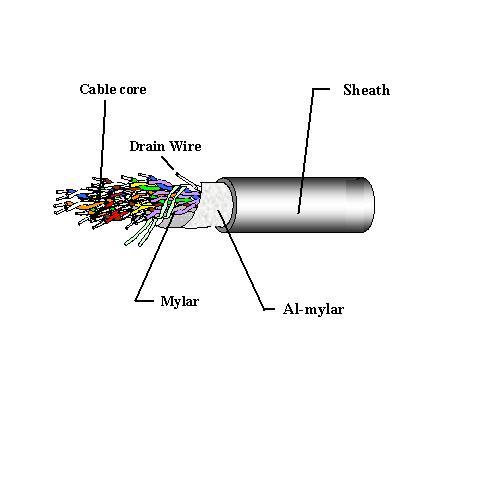
This cable is a polyethylene insulated, PVC sheathed, unit type cable for indoor installation. 1. Scope This cable is a polyethylene insulated, PVC sheathed, unit type cable for indoor installation. 2. Wire Construction: Wire Quad NO. A-wire B-wire C-wire D-wire 1 Blue White Brown Black 2 Yellow White Brown Black 3 Green White Brown Black 4 Red White Brown Black 5 Violet White Brown Black 3.Core Forming: 6P~200P Pair PE tape Pair PE tape pair PE tape 1-10P Blue-Blue 71-80P Green-White 141-150P Violet-Brown 11-20P Yellow-Yellow 81-90P Red-White 151-160P Blue-Black 21-30P Green-Green 91-100P Violet-White 161-170P Yellow-Black 31-40P Red-Red 101-110P Blue-Brown 171-180P Green-Black 41-50P Violet-Violet 111-120P Yellow-Brown 181-190P Red-Black 51-60P Blue-White 121-130P Green-Brown 191-200P Violet-Black 61-70P Yellow-White 131-140P Red-Brown 300P~600P Pair PE tape Pair PE tape pair PE tape 1-50P Blue-Blue 201-250P Violet-Violet 401-450P Red-White 51-100P Yellow-Yellow 251-300P Blue-White 451-500P Violet-White 1011-150P Green-Green 301-350P Yellow-White 501-550P Blue-Brown 151-200P Red-Red 351-400P Green-White 551-600P Yellow-Brown 4.Structure: 4.1. Conductor:0.4±0.01mm、0.5±0.01mm 4.2. Number of pair:6、10、20、30、50、100、200、300、400、600 4.3. Insulation:PE 4.4. Twisted:Four insulated conductor shall be twisted together 4.5. Assembly:Arranged in accordance with the structure figure 4.6. Core Wrap:0.025mm Thickness , mylar tape Min(overlap ratio 33%) 4.7. Drain wire:7/0.16 Tinned Copper Wire 4.8. Shield:0.05mm Thickness , Al-mylar tape Min(overlap ratio 33%) ,with Al side in 4.9. Sheath:PE 5. Standards: Dia. of conductor (mm) No. of pair (P) Insulation thickness (mm) cable core diameter (mm) approx. Sheath thickness (mm) overall diameter (mm) approx. estimated weight (Kg/m) Standard length (M) 6 0.13 4 1.3 7 52 500 10 0.13 5 1.3 8 69 500 20 0.13 6 1.3 9 109 500 30 0.13 7 1.3 10 143 500 0.4 50 0.13 10 1.4 13 218 500 100 0.13 14 1.6 17 397 500 200 0.13 18 1.9 22 746 500 300 0.13 23 2.0 27 1076 500 400 0.13 26 2.3 31 1427 500 600 0.13 31 2.4 36 2061 500 6 0.15 5 1.3 8 67 500 10 0.15 6 1.3 9 90 500 20 0.15 7 1.3 10 146 500 30 0.15 9 1.3 12 198 500 0.5 50 0.15 12 1.4 15 309 500 100 0.15 16 1.6 20 565 500 200 0.15 22 2.0 26 1087 500 300 0.15 27 2.1 31 1577 500 400 0.15 31 2.4 36 2092 500 600 0.15 38 2.5 43 3044 500 6. Electric Properties: Item 0.4 0.5 Conductor resistance Standard value:139Ω/KMMax. value:147.5Ω/KM Standard value:88.7Ω/KMMax. value:93.5Ω/KM Mutual capacitance 50P↑→ 55 nf/km ↓,30P ↓→ 60 nf/km ↓ Dielectric strength DC 500V / 1min. or AC 350 V / 1min. Insulation resistance 5000MW- Km DC 250~500V Near-End Cross-talk 40KHz,AC Min value:58.5dB↑Average value:66dB↑ Far-End Cross-talk 160KHz,AC m-1.28×S≧55dB/㎞以上 m:Average value S:Standard value Min value:38dB/km↑
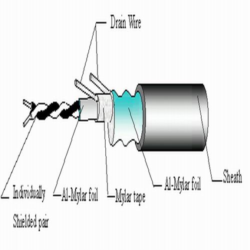
This cable is used for interconnecting between frames of PCM equipments with 120W characteristic impedance. 1.Application:This cable is used for interconnecting between frames of PCM equipments with 120W characteristic impedance.2. Conductor:Annealed bare copper or tinned copper3. Insulation:Foamed PE / HDPE4.Shielded:Two wires are twisted to form a pair then shielded with a layer of Al-Mylar foil. A piece of tinned copper wire is added along with the pair as drain wire.5.Assembly:Suitable number of pairs are assembled to form a cable core.6. Overall shield:a. Layer of Al-Mylar foil with a drain wire.7.Sheath:PVC (polyvinyl Chloride)or LSNHFRPE.( ow-moke Non-Halogen Flame Retardant Polyethylene). 8. Structure: Conducyor Pair Insulation Cable core Sheath Overall Standard Diameter(mm) (P) Diameter(mm) Diameter(mm) Thickness(mm) Diameter(mm) Length(M) 0.5 1 1.3 3.5 0.6 5.0 200 2 6.0 0.6 7.5 200 4 7.0 0.6 8.5 500 8 10.0 0.6 11.5 500 10 10.0 0.6 11.5 500 16 13.5 0.8 16.0 500 22 16.0 1.0 18.3 500 25 16.0 1.0 18.5 500 32 19.0 1.0 21.5 500 40 21.0 1.5 24.5 500 9. Characteristics: Items Specification Conductor Resistance ( 20℃ ) Max.100.2W / Km Conductor Resistance unbalance( 20℃ ) Max.5 ﹪ Insulation Resistance ( 20℃,DC 500V / 1min.) Min .5000M - Km Dielectric strength DC 1000V / 1min. Between Conductors DC 1500V / 1min. Between Conductors and shield Static Capacitance (1KHz) Max.50 nf / Km Attenuation. (1024 KHz) Max.34 dB / Km Characteristic Impedance (1024 KHz) 120 ± 10W Near-end cross talk (1024 KHz) Min.70 dB / 500M 10. Marking:TATUNG CO. PCM – E1 0.5 ´ð P yearðM
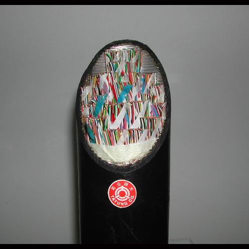
This specification describes the Foam Skin insulated, star quad, polyethylene sheathed, aluminum and steel tape shielded (Stalpeth) telephone cable used for trunking between telephone stations and subscribers. 1. Scope : This specification describes the Foam Skin insulated, star quad, polyethylene sheathed, aluminum and steel tape shielded (Stalpeth) telephone cable used for trunking between telephone stations and subscribers. 2. Conductor:0.4、0.5、0.65、0.9 3.Insulation:Foam-skin PE 4. Twisted:Four insulated conductor shall be twisted together 5. Assembly:Arranged in accordance with the structure figure 6. Core Wrap:Mylar tape、Non-woven wrapping tape、 non-woven water blocking tape 7. Aluminum tape and Tinned steel tape: (1) A single shield of aluminum tape shall be applied longitudinally, thickness 0.2±0.05mm. (2) A single shield of tinned steel tape shall be applied longitudinally, thickness 0.18±0.05mm. (3) The outer layer of steel tape shall be homogeneously covered with one layer of non-hydroscopic flooding compound. 8. Sheath:Polyethylene sheath 9. diameter of conductor (mm) number of pairs (P) standard thickness of insulation (mm) cable core diameter (mm) appro. width of longitudinal laid tape (mm) appro. thickness of PE sheath (mm) overall diameter (mm) appro. gross weight (Kg/M) appro. 400 0.11 26 25 1.5 32 1.57 600 0.11 31 30 1.6 38 2.20 800 0.11 35 30 1.8 42 2.81 1000 0.11 40 35 1.9 48 3.40 1200 0.11 43 35 2.0 51 4.08 1400 0.11 47 40 2.1 55 4.69 1600 0.11 50 40 2.2 58 5.29 0.4 1800 0.11 52 40 2.3 61 5.88 2000 0.11 54 40 2.4 63 6.47 2200 0.11 57 40 2.5 66 7.06 2400 0.11 59 40 2.5 68 7.56 2600 0.11 61 40 2.6 70 8.24 2800 0.11 64 45 2.7 73 8.83 3000 0.11 66 45 2.8 76 9.45 3200 0.11 68 45 3.0 78 10.06 400 0.13 31 25 1.6 38 2.21 600 0.13 38 35 1.8 45 3.14 800 0.13 42 35 1.9 50 4.05 1000 0.13 48 40 2.1 56 4.97 1200 .013 53 40 2.3 61 5.96 0.5 1400 0.13 57 40 2.5 66 6.88 1600 0.13 60 40 2.5 70 7.75 1800 0.13 63 40 2.6 72 8.63 2000 0.13 66 45 2.8 76 9.64 2200 0.13 69 45 3.0 79 10.45 2400 0.13 72 45 3.0 82 11.31 400 0.15 38 35 1.8 45 3.42 600 0.15 47 40 2.1 55 4.97 0.65 800 0.15 53 40 2.3 61 6.45 100 0.15 59 40 2.5 68 7.95 1200 0.15 65 45 2.8 74 9.47 1400 0.15 70 45 3.0 80 10.96 0.9 400 0.21 52 40 2.3 61 6.19 10.Electric Properties: Item 0.4 0.5 0.65 0.9 Conductor resistance Standard value:139Ω/KMMax. value:147.5Ω/KM Standard value:88.7Ω/KMMax. value:93.5Ω/KM Standard value:52.5Ω/KMMax. value:56.5Ω/KM Standard value:27.4Ω/KMMax. value:29.0Ω/KM Dielectric strength DC 500V / 1min. or AC 350 V / 1min. Insulation resistance 5000MW- Km DC 250~500V Near-End Cross-talk 40KHz,AC Min value:58.5dB↑Average value:66dB↑ Far-End Cross-talk 160KHz,AC m-1.28×S≧55dB/㎞以上 m:Average value S:Standard value Min value:38dB/km↑
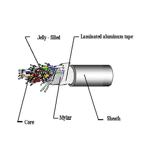
This cable is a Foam Skin insulated, jelly filled, laminated sheathed, unit type cable for underground local telephone network, abbreviated to FS-JF-LAP cable. 1. Scope: This cable is a Foam Skin insulated, jelly filled, laminated sheathed, unit type cable for underground local telephone network, abbreviated to FS-JF-LAP cable. 2. Wire Construction: Wire Quad NO. A-wire B-wire C-wire D-wire 1 Blue White Brown Black 2 Yellow White Brown Black 3 Green White Brown Black 4 Red White Brown Black 5 Violet White Brown Black 3.Core Forming: 10P~200P Pair PE tape Pair PE tape pair PE tape 1-10P Blue-Blue 71-80P Green-White 141-150P Violet-Brown 11-20P Yellow-Yellow 81-90P Red-White 151-160P Blue-Black 21-30P Green-Green 91-100P Violet-White 161-170P Yellow-Black 31-40P Red-Red 101-110P Blue-Brown 171-180P Green-Black 41-50P Violet-Violet 111-120P Yellow-Brown 181-190P Red-Black 51-60P Blue-White 121-130P Green-Brown 191-200P Violet-Black 61-70P Yellow-White 131-140P Red-Brown 300P~600P Pair PE tape Pair PE tape pair PE tape 1-50P Blue-Blue 201-250P Violet-Violet 401-450P Red-White 51-100P Yellow-Yellow 251-300P Blue-White 451-500P Violet-White 1011-150P Green-Green 301-350P Yellow-White 501-550P Blue-Brown 151-200P Red-Red 351-400P Green-White 551-600P Yellow-Brown 4.Structure: 4.1. Conductor:0.4± 0.01mm 、0.5± 0.01mm 、0.65± 0.02mm 4.2. Number of pair:10、20、30、50、100、200、300、400、600 4.3. Insulation: Foam-skin PE 4.4. Twisted:Four insulated conductor shall be twisted together 4.5. Assembly:Arranged in accordance with the structure figure 4.6. Jelly-filled:Jelly compound should be filled the space within the cable core. 4.7. Core Wrap:Non – hygroscopic dielectric tape 4.8. Shield:Laminated Aluminum shield 0.2mm thickness, longitudinally laid on with over lap. 4.9. Sheath:PE5. Standards: Dia. of conductor (mm) Number of pairs (P) Insulation thickness (mm) cable core diameter (mm) approx. Sheath thickness (mm) overall diameter (mm) approx. estimated weight (Kg/m) Standard length (M) 0.4 10 0.13 5.5 1.7 9 0.09 500 0.4 20 0.13 7.0 1.7 11 0.13 500 0.4 30 0.13 8.5 1.7 12 0.18 500 0.4 50 0.13 10 1.7 14 0.25 500 0.4 100 0.13 14 1.7 18 0.44 500 0.4 200 0.13 20 1.7 24 0.80 500 0.4 300 0.13 24 1.9 28 1.15 500 0.4 400 0.13 28 2.0 33 1.60 500 0.4 600 0.13 33 2.2 39 2.27 500 0.5 10 0.15 6.5 1.7 10 0.11 500 0.5 20 0.15 8.0 1.7 12 0.18 500 0.5 30 0.15 10 1.7 14 0.24 500 0.5 50 0.15 12 1.7 16 0.35 500 0.5 100 0.15 17 1.7 21 0.63 500 0.5 200 0.15 23 1.8 27 1.16 500 0.5 300 0.15 29 2.0 34 1.67 500 0.5 400 0.15 33 2.2 39 2.30 500 0.5 600 0.15 39 2.3 45 3.20 500 0.65 10 0.20 8 1.7 12 0.16 500 0.65 20 0.20 11 1.7 15 0.28 500 0.65 30 0.20 13 1.7 17 0.36 500 0.65 50 0.20 16 1.7 20 0.54 500 0.65 100 0.20 23 1.8 27 1.00 500 0.65 200 0.20 31 2.0 36 1.85 500 0.65 300 0.20 37 2.2 42 2.76 500 0.65 400 0.20 42 2.3 48 3.80 500 0.65 600 0.20 51 2.6 57 5.40 345 Item 0.4 0.5 0.65 Conductor resistance Standard value:139Ω/KMMax. value:147.5Ω/KM Standard value:88.7Ω/KMMax. value:93.5Ω/KM Standard value:52.5Ω/KMMax. value:56.5Ω/KM Mutual capacitance 50P↑→ 55 nf/km ↓,30P ↓→ 60 nf/km ↓ Dielectric strength DC 500V / 1min. or AC 350 V / 1min. Insulation resistance 5000MW- Km DC 250~500V Near-End Cross-talk 40KHz,AC Min value:58.5dB↑Average value:66dB↑ Far-End Cross-talk 160KHz,AC m-1.28×S≧55dB/㎞以上 m:Average value S:Standard value Min value:38dB/km↑
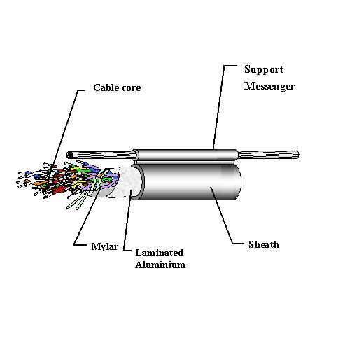
This cable is a polyethylene insulated, laminated-sheathed, unit type cable. 1. Scope: This cable is a polyethylene insulated, laminated-sheathed, unit type cable. 2. Wire Construction: Wire Quad NO. A-wire B-wire C-wire D-wire 1 Blue White Brown Black 2 Yellow White Brown Black 3 Green White Brown Black 4 Red White Brown Black 5 Violet White Brown Black 3.Core Forming: 10P~200P Pair PE tape Pair PE tape pair PE tape 1-10P Blue-Blue 71-80P Green-White 141-150P Violet-Brown 11-20P Yellow-Yellow 81-90P Red-White 151-160P Blue-Black 21-30P Green-Green 91-100P Violet-White 161-170P Yellow-Black 31-40P Red-Red 101-110P Blue-Brown 171-180P Green-Black 41-50P Violet-Violet 111-120P Yellow-Brown 181-190P Red-Black 51-60P Blue-White 121-130P Green-Brown 191-200P Violet-Black 61-70P Yellow-White 131-140P Red-Brown 300P~600P Pair PE tape Pair PE tape pair PE tape 1-50P Blue-Blue 201-250P Violet-Violet 401-450P Red-White 51-100P Yellow-Yellow 251-300P Blue-White 451-500P Violet-White 1011-150P Green-Green 301-350P Yellow-White 501-550P Blue-Brown 151-200P Red-Red 351-400P Green-White 551-600P Yellow-Brown 4.Structure: 4.1. Conductor:0.4± 0.01mm、0.5± 0.01mm、0.65± 0.02mm、0.9± 0.02mm 4.2. Number of pair:10、20、30、50、100、200、300、400、600 4.3. Insulation:PE 4.4. Twisted:Four insulated conductor shall be twisted together 4.5. Assembly:Arranged in accordance with the structure figure 4.6. Core Wrap:Non – hygroscopic dielectric tape 4.7. Shield:Laminated Aluminum shield 0.2mm thickness, longitudinally laid on with over lap. 4.8. Support Messenger:Galvanized steel wire 4.9. Sheath:PE 5. Standards: Dia. of conductor (mm) No. of pair (P) Insulation thickness (mm) Sheath thickness (mm) Galvanized steel wire Standard length (M) No./mm Sheath thickness (mm) CCP-LAP CCP-LAP-SS 0.4 10 0.13 1.7 7/1.8 1.0 500 1000 0.4 20 0.13 1.7 7/1.8 1.0 500 1000 0.4 30 0.13 1.7 7/1.8 1.0 500 1000 0.4 50 0.13 1.7 7/1.8 1.0 500 500 0.4 100 0.13 1.7 7/1.8 1.0 500 500 0.4 200 0.13 1.7 7/2.0 1.0 500 500 0.4 300 0.13 1.9 - - 500 - 0.4 400 0.13 2.0 - - 500 - 0.4 600 0.13 2.1 - - 500 - 0.5 10 0.15 1.7 7/1.8 1.0 500 1000 0.5 20 0.15 1.7 7/1.8 1.0 500 1000 0.5 30 0.15 1.7 7/1.8 1.0 500 1000 0.5 50 0.15 1.7 7/1.8 1.0 500 500 0.5 100 0.15 1.7 7/2.0 1.0 500 500 0.5 200 0.15 1.8 7/2.3 1.2 500 500 0.5 300 0.15 2.0 - - 500 - 0.5 400 0.15 2.1 - - 500 - 0.5 600 0.15 2.3 - - 500 - 0.65 10 0.20 1.7 7/1.8 1.0 500 1000 0.65 20 0.20 1.7 7/1.8 1.0 500 1000 0.65 30 0.20 1.7 7/1.8 1.0 500 1000 0.65 50 0.20 1.7 7/2.0 1.0 500 500 0.65 100 0.20 1.8 7/2.3 1.2 500 500 0.65 200 0.20 2.0 - - 500 - 0.65 300 0.20 2.2 - - 345 - 0.65 400 0.20 2.3 - - 345 - 0.65 600 0.20 2.6 - - 345 - 0.9 10 0.27 1.7 7/1.8 1.0 500 500 0.9 20 0.27 1.7 7/1.8 1.0 500 500 0.9 30 0.27 1.7 7/2.0 1.0 500 500 0.9 50 0.27 1.8 7/2.3 1.2 500 500 0.9 100 0.27 2.0 - - 500 - 6. Electric Properties: Item 0.4 0.5 0.65 0.9 Conductor resistance Standard value:139Ω/KMMax. value:147.5Ω/KM Standard value:88.7Ω/KMMax. value:93.5Ω/KM Standard value:52.5Ω/KMMax. value:56.5Ω/KM Standard value:27.4Ω/KMMax. value:29.0Ω/KM Mutual capacitance 50P↑→ 55 nf/km ↓,30P(含) ↓→ 60 nf/km ↓ Dielectric strength DC 500V / 1min. or AC 350 V / 1min. Insulation resistance 5000MW- Km DC 250~500V Near-End Cross-talk 40KHz,AC Min value:58.5dB↑Average value:66dB↑ Far-End Cross-talk 160KHz,AC m-1.28×S≧55dB/㎞以上 m:Average value S:Standard value Min value:38dB/km↑
UEYW UEYW (Polyurethane overcoated with nylon copper magnet wire) is used to communication instrument, tiny transformer, electric fan, motor ,relay, fluorescent lamp stabilizer and deflection yoke. Features Designation UEYW UEYW-F UEYW-H Thermal Class B (130℃) F (155℃) H (180℃) Structure Heat Shock 175℃ 175℃ 200℃ Thermoplastic Flow(Not less than ) 200℃ 200℃ 225℃ Solderability 390℃ Feature 1.Solderable 2.Good high speed coiling performance Application Communication instrumentTiny transformerElectric fanMotorRelayFluorescent lamp stabilizerDeflection yoke Specifications ‧Thermal class : B (130℃), F (155℃), H (180℃)‧Wire diameter : 0.03 ~ 2.60 mm for B and F class 0.03 ~ 0.50 mm for H class‧Applicable standards : CNS C2170 NEMA MW 28-C (B class) UL Recognized (UEYW and UEYW-F) IEC 317-19 (B class) NEMA MW 80-C (F class) IEC 317-21 ( F class) NEMA MW 83-C ( H class)‧Plastic Bobbin Diameter: Symbol Capacity (kg) PL-3G 0.3 PL-5G 0.5 P-3 3 PT-1 1.5 PT-2 2 PT-4 4 PT-10 10 PT-15 15 PT-18 18 PT-25 25 PT-60 60 PT-90 90 PT-190 190 PT-270 270 ‧JIS Specification of Magnet copper wire Conductor Class 0 Class 1 Max. conductorresistance(W / km 20℃) Diameter(mm) Tolerance(mm) Min. film thickness(mm) Max. overall diameter(mm) Min. film thickness(mm) Max. overall diameter(mm) 0.100.110.120.130.14 ±0.008±0.008±0.008±0.008±0.008 0.0160.0160.0170.0170.017 0.1560.1660.1800.1900.200 0.0090.0090.0100.0100.010 0.1400.1500.1620.1720.182 2647.0002153.0001786.0001505.0001286.000 0.150.160.170.180.19 ±0.008±0.008±0.008±0.008±0.008 0.0170.0180.0180.0190.019 0.2100.2220.2320.2460.256 0.010.0.0110.0110.0120.012 0.1920.2040.2140.2260.236 1111.000969.500853.500757.200676.200 0.200.210.220.230.24 ±0.008±0.008±0.008±0.008±0.008 0.0190.0190.0190.0200.020 0.2660.2760.2860.2980.308 0.0120.0120.0120.0130.013 0.2460.2560.2660.2780.288 607.600549.000498.400454.500416.200 0.250.260.270.280.29 ±0.008±0.010±0.010±0.010±0.010 0.0200.0200.0200.0200.020 0.3180.3300.3400.3500.360 0.0130.0130.0130.0130.013 0.2980.3100.3200.3300.340 382.500358.400331.400307.300285.700 0.300.320.350.370.40 ±0.010±0.010±0.010±0.010±0.010 0.0210.0210.0210.0220.023 0.3740.3940.4240.4460.480 0.0140.0140.0140.0140.015 0.3520.3720.4020.4240.456 262.900230.000191.200170.600145.300 0.450.500.550.600.65 ±0.010±0.010±0.020±0.020±0.020 0.0240.0250.0250.0260.027 0.5320.5860.6460.6980.752 0.0160.0170.0170.0170.018 0.5080.5600.6200.6720.724 114.20091.43078.15065.26055.310 0.700.750.800.850.90 ±0.020±0.020±0.020±0.020±0.020 0.0280.0300.0310.0320.033 0.8040.8600.9140.9661.020 0.0190.0200.0210.0220.023 0.7760.8300.8820.9340.986 47.47041.19036.08031.87028.350 0.951.001.101.201.30 ±0.020±0.030±0.030±0.030±0.030 0.0340.0360.0370.0370.039 1.0721.1381.2421.3421.448 0.0240.0250.0260.0260.027 1.0381.1021.2041.3041.408 25.38023.33019.17016.04013.610 1.401.501.601.701.80 ±0.030±0.030±0.030±0.030±0.030 0.0390.0410.0410.0420.042 1.5481.6541.7541.8561.956 0.0270.0280.0280.0290.029 1.5081.6121.7121.8141.914 11.70010.1608.9067.8717.007 1.902.002.102.202.30 ±0.030±0.030±0.030±0.030±0.030 0.0440.0440.0450.0460.046 2.0622.1622.2662.3682.468 0.0300.0300.0310.0320.032 2.0182.1182.2202.3222.422 6.2785.6565.1234.6624.260 2.402.502.60 ±0.030±0.030±0.030 0.04800490.049 2.5742.6782.778 0.0330.0340.034 2.5262.6282.728 3.9083.5983.324 Conductor Class 2 Max. conductor resistance(W / km 20℃) Diameter(mm) Tolerance(mm) Min. film thickness(mm) Max. overall diameter(mm) 0.030.040.050.060.07 ±0.002±0.002±0.003±0.003±0.003 0.0030.0030.0040.0040.004 0.0440.0560.0690.0810.091 28,870.0015,670.0010,240.006,966.004,990.00 0.080.090.100.110.12 ±0.003±0.003±0.003±0.003±0.003 0.0050.0050.0050.0050.006 0.1030.1130.1250.1350.147 3,778.002,959.002,381.001,957.001,636.00 0.130.140.150.160.17 ±0.003±0.003±0.003±0.003±0.003 0.0060.0060.0060.0070.007 0.1570.1670.1770.1890.199 1,389.001,193.001,037.00908.80803.20 0.180.190.200.210.22 ±0.003±0.003±0.003±0.003±0.004 0.0080.0080.0080.0080.008 0.2110.2210.2310.2410.252 715.00640.60577.20522.80480.10 0.230.240.250.260.27 ±0.004±0.004±0.004±0.004±0.004 0.0090.0090.0090.0090.009 0.2640.2740.2840.2940.304 438.10402.20370.20341.80316.60 0.280.290.300.320.35 ±0.004±0.004±0.005±0.005±0.005 0.0090.0090.0100.0100.010 0.3140.3240.3370.3570.387 294.10273.90254.00222.80185.70 0.370.400.450.500.55 ±0.005±0.005±0.006±0.006±0.006 0.0100.0110.0110.0120.012 0.4070.4390.4900.5420.592 165.90141.70112.1089.9574.18 0.600.650.700.750.80 ±0.008±0.008±0.008±0.008±0.010 0.0120.0120.0130.0140.015 0.6440.6940.7460.7980.852 62.6453.2645.8439.8735.17 0.850.900.951.00 ±0.010±0.010±0.010±0.012 0.0150.0160.0170.017 0.9040.9561.0081.062 31.1127.7124.8422.49 ‧NEMA Specification of Magnet copper wire AWGSIZE Nom.Diameter (mm) Single Build Heavy Build Min. film thickness(mm) Max. overall diameter(mm) Min. film thickness(mm) Max. overall diameter(mm) 44 0.051 0.0025 0.061 0.005 0.069 43 0.056 0.0025 0.066 0.005 0.074 42 0.064 0.0025 0.076 0.0065 0.084 41 0.071 0.004 0.086 0.0065 0.091 40 0.079 0.004 0.094 0.0065 0.102 39 0.089 0.004 0.104 0.0075 0.114 38 0.102 0.004 0.119 0.009 0.130 37 0.114 0.005 0.135 0.009 0.145 36 0.127 0.005 0.147 0.010 0.160 35 0.142 0.005 0.163 0.0115 0.178 34 0.160 0.0065 0.183 0.0115 0.198 33 0.180 0.0065 0.206 0.0125 0.224 32 0.203 0.0075 0.231 0.014 0.249 31 0.226 0.0075 0.254 0.015 0.274 30 0.254 0.009 0.284 0.0165 0.302 29 0.287 0.009 0.320 0.019 0.338 28 0.32 0.010 0.356 0.0205 0.373 27 0.361 0.010 0.396 0.0205 0.419 26 0.404 0.012 0.439 0.0215 0.462 25 0.455 0.0115 0.493 0.023 0.516 24 0.511 0.0125 0.551 0.024 0.577 23 0.574 0.0125 0.617 0.0255 0.643 22 0.643 0.014 0.686 0.0265 0.714 21 0.724 0.014 0.770 0.028 0.800 20 0.813 0.015 0.864 0.0305 0.892 19 0.912 0.015 0.963 0.032 0.993 18 1.024 0.0165 1.077 0.033 1.110 17 1.151 0.018 1.207 0.0355 1.240 16 1.29 0.018 1.349 0.037 1.384 15 1.45 0.019 1.509 0.038 1.549 14 1.628 0.0205 1.692 0.0405 1.732 13 1.829 0.0205 1.892 0.0405 1.934 12 2.052 0.0205 2.117 0.0405 2.163 11 2.304 0.0215 2.373 0.042 2.418 10 2.588 0.0215 2.660 0.043 2.703
UEW UEW (Polyurethane copper magnet wire) is used to tiny transformer, motor, relay, electric fan, TV, monitor flying back transformer and ignition coil. Features Designation UEW UEW-F UEW-H Thermal Class B (130℃) F (155℃) H (180℃) Structure Heat Shock 175℃ 175℃ 200℃ Thermoplastic Flow(Not less than ) 200℃ 200℃ 225℃ Solderability 390℃ Feature 1.Solderable 2.Color adjustable Application Tiny transformerMotorRelayElectric fanTVMonitor flying back transformerIgnition coil Specifications ‧Thermal class : B (130℃), F (155℃), H (180℃)‧Wire diameter : 0.03 ~ 2.60 mm for B and F class 0.03 ~ 0.50 mm for H class‧Applicable standards : CNS C2041 JIS-C3202-6 NEMA MW 75-C (B class) UL Recognized (UEW) IEC 317-4 (B class) NEMA MW 79-C (F class) IEC 317-20 ( F class) NEMA MW 82-C ( H class) IEC 317-51 ( H class)‧Plastic Bobbin Diameter: Symbol Capacity (kg) PL-3G 0.3 PL-5G 0.5 P-3 3 PT-1 1.5 PT-2 2 PT-4 4 PT-10 10 PT-15 15 PT-18 18 PT-25 25 PT-60 60 PT-90 90 PT-190 190 PT-270 270 ‧JIS Specification of Magnet copper wire Conductor Class 0 Class 1 Max. conductorresistance(W / km 20℃) Diameter(mm) Tolerance(mm) Min. film thickness(mm) Max. overall diameter(mm) Min. film thickness(mm) Max. overall diameter(mm) 0.100.110.120.130.14 ±0.008±0.008±0.008±0.008±0.008 0.0160.0160.0170.0170.017 0.1560.1660.1800.1900.200 0.0090.0090.0100.0100.010 0.1400.1500.1620.1720.182 2647.0002153.0001786.0001505.0001286.000 0.150.160.170.180.19 ±0.008±0.008±0.008±0.008±0.008 0.0170.0180.0180.0190.019 0.2100.2220.2320.2460.256 0.010.0.0110.0110.0120.012 0.1920.2040.2140.2260.236 1111.000969.500853.500757.200676.200 0.200.210.220.230.24 ±0.008±0.008±0.008±0.008±0.008 0.0190.0190.0190.0200.020 0.2660.2760.2860.2980.308 0.0120.0120.0120.0130.013 0.2460.2560.2660.2780.288 607.600549.000498.400454.500416.200 0.250.260.270.280.29 ±0.008±0.010±0.010±0.010±0.010 0.0200.0200.0200.0200.020 0.3180.3300.3400.3500.360 0.0130.0130.0130.0130.013 0.2980.3100.3200.3300.340 382.500358.400331.400307.300285.700 0.300.320.350.370.40 ±0.010±0.010±0.010±0.010±0.010 0.0210.0210.0210.0220.023 0.3740.3940.4240.4460.480 0.0140.0140.0140.0140.015 0.3520.3720.4020.4240.456 262.900230.000191.200170.600145.300 0.450.500.550.600.65 ±0.010±0.010±0.020±0.020±0.020 0.0240.0250.0250.0260.027 0.5320.5860.6460.6980.752 0.0160.0170.0170.0170.018 0.5080.5600.6200.6720.724 114.20091.43078.15065.26055.310 0.700.750.800.850.90 ±0.020±0.020±0.020±0.020±0.020 0.0280.0300.0310.0320.033 0.8040.8600.9140.9661.020 0.0190.0200.0210.0220.023 0.7760.8300.8820.9340.986 47.47041.19036.08031.87028.350 0.951.001.101.201.30 ±0.020±0.030±0.030±0.030±0.030 0.0340.0360.0370.0370.039 1.0721.1381.2421.3421.448 0.0240.0250.0260.0260.027 1.0381.1021.2041.3041.408 25.38023.33019.17016.04013.610 1.401.501.601.701.80 ±0.030±0.030±0.030±0.030±0.030 0.0390.0410.0410.0420.042 1.5481.6541.7541.8561.956 0.0270.0280.0280.0290.029 1.5081.6121.7121.8141.914 11.70010.1608.9067.8717.007 1.902.002.102.202.30 ±0.030±0.030±0.030±0.030±0.030 0.0440.0440.0450.0460.046 2.0622.1622.2662.3682.468 0.0300.0300.0310.0320.032 2.0182.1182.2202.3222.422 6.2785.6565.1234.6624.260 2.402.502.60 ±0.030±0.030±0.030 0.04800490.049 2.5742.6782.778 0.0330.0340.034 2.5262.6282.728 3.9083.5983.324 Conductor Class 2 Max. conductor resistance(W / km 20℃) Diameter(mm) Tolerance(mm) Min. film thickness(mm) Max. overall diameter(mm) 0.030.040.050.060.07 ±0.002±0.002±0.003±0.003±0.003 0.0030.0030.0040.0040.004 0.0440.0560.0690.0810.091 28,870.0015,670.0010,240.006,966.004,990.00 0.080.090.100.110.12 ±0.003±0.003±0.003±0.003±0.003 0.0050.0050.0050.0050.006 0.1030.1130.1250.1350.147 3,778.002,959.002,381.001,957.001,636.00 0.130.140.150.160.17 ±0.003±0.003±0.003±0.003±0.003 0.0060.0060.0060.0070.007 0.1570.1670.1770.1890.199 1,389.001,193.001,037.00908.80803.20 0.180.190.200.210.22 ±0.003±0.003±0.003±0.003±0.004 0.0080.0080.0080.0080.008 0.2110.2210.2310.2410.252 715.00640.60577.20522.80480.10 0.230.240.250.260.27 ±0.004±0.004±0.004±0.004±0.004 0.0090.0090.0090.0090.009 0.2640.2740.2840.2940.304 438.10402.20370.20341.80316.60 0.280.290.300.320.35 ±0.004±0.004±0.005±0.005±0.005 0.0090.0090.0100.0100.010 0.3140.3240.3370.3570.387 294.10273.90254.00222.80185.70 0.370.400.450.500.55 ±0.005±0.005±0.006±0.006±0.006 0.0100.0110.0110.0120.012 0.4070.4390.4900.5420.592 165.90141.70112.1089.9574.18 0.600.650.700.750.80 ±0.008±0.008±0.008±0.008±0.010 0.0120.0120.0130.0140.015 0.6440.6940.7460.7980.852 62.6453.2645.8439.8735.17 0.850.900.951.00 ±0.010±0.010±0.010±0.012 0.0150.0160.0170.017 0.9040.9561.0081.062 31.1127.7124.8422.49 ‧NEMA Specification of Magnet copper wire AWGSIZE Nom.Diameter (mm) Single Build Heavy Build Min. film thickness(mm) Max. overall diameter(mm) Min. film thickness(mm) Max. overall diameter(mm) 44 0.051 0.0025 0.061 0.005 0.069 43 0.056 0.0025 0.066 0.005 0.074 42 0.064 0.0025 0.076 0.0065 0.084 41 0.071 0.004 0.086 0.0065 0.091 40 0.079 0.004 0.094 0.0065 0.102 39 0.089 0.004 0.104 0.0075 0.114 38 0.102 0.004 0.119 0.009 0.130 37 0.114 0.005 0.135 0.009 0.145 36 0.127 0.005 0.147 0.010 0.160 35 0.142 0.005 0.163 0.0115 0.178 34 0.160 0.0065 0.183 0.0115 0.198 33 0.180 0.0065 0.206 0.0125 0.224 32 0.203 0.0075 0.231 0.014 0.249 31 0.226 0.0075 0.254 0.015 0.274 30 0.254 0.009 0.284 0.0165 0.302 29 0.287 0.009 0.320 0.019 0.338 28 0.32 0.010 0.356 0.0205 0.373 27 0.361 0.010 0.396 0.0205 0.419 26 0.404 0.012 0.439 0.0215 0.462 25 0.455 0.0115 0.493 0.023 0.516 24 0.511 0.0125 0.551 0.024 0.577 23 0.574 0.0125 0.617 0.0255 0.643 22 0.643 0.014 0.686 0.0265 0.714 21 0.724 0.014 0.770 0.028 0.800 20 0.813 0.015 0.864 0.0305 0.892 19 0.912 0.015 0.963 0.032 0.993 18 1.024 0.0165 1.077 0.033 1.110 17 1.151 0.018 1.207 0.0355 1.240 16 1.29 0.018 1.349 0.037 1.384 15 1.45 0.019 1.509 0.038 1.549 14 1.628 0.0205 1.692 0.0405 1.732 13 1.829 0.0205 1.892 0.0405 1.934 12 2.052 0.0205 2.117 0.0405 2.163 11 2.304 0.0215 2.373 0.042 2.418 10 2.588 0.0215 2.660 0.043 2.703
TSB TSB (Thermal endurance self-bonding copper magnet wire) is a construction of bondable wire, having PEW-H / PEW-HC / PEW-HS base insulation with a thermoplastic bondcoat which may be activated by heat. Thermoplastic bondcoat temperature is higher than SB. TSB magnet wire is used to voice coils, special motor and coreless coil. Features Designation TSBPEW-H TSBPEW-HC TSBPEW-HS Thermal Class H (180℃) N (200℃) H (180℃) Structure Heat Shock 200℃ 220℃ 200℃ Thermoplastic flow(Not less than ) 300℃ 300℃ 225℃ Solderability - 470℃ Self-bonding process 400~450℃ (different from custom’s process) Feature 1.Special thermal endurance of SB layer 2.same as PEW-H / PEW-HC / PEW-HS Application Special motorCoreless coilVoice coils Specifications ‧Thermal class : H (180℃), N(200℃)‧Wire diameter : 0.03 ~ 1.00 mm ‧Applicable standards : NEMA MW102-C (TSBPEW-H H class) UL Recognized (TSB-PEW-H) IEC 317-38 (TSBPEW-HC N class)‧Plastic Bobbin Diameter: Symbol Capacity (kg) PL-3G 0.3 PL-5G 0.5 P-3 3 PT-1 1.5 PT-2 2 PT-4 4 PT-10 10 PT-15 15 PT-18 18 PT-25 25 PT-60 60 PT-90 90 PT-190 190 PT-270 270 ‧JIS Specification of Magnet copper wire Diameter(mm) Class 0 Class 1 Class 2 Min. film thickness(mm) Max. overall diameter(mm) Max. conductorresistance(W / km 20℃) Min. film thickness(mm) Max. overall diameter(mm) Max. conductorresistance(W / km 20℃) Min. film thickness(mm) Max. overall diameter(mm) Max. conductorresistance(W / km 20℃) SB BC SB BC SB BC 0.10 - - 0.002 0.003 0.037 42780 0.11 0.044 28870 0.12 0.056 15670 0.13 0.004 0.005 0.083 10700 0.003 0.004 0.069 10240 0.14 0.006 0.096 7761 0.081 6966 0.15 0.106 5469 0.091 4990 0.16 0.005 0.007 0.118 4091 0.005 0.103 3778 0.17 0.008 0.128 3175 0.113 2959 0.18 0.009 0.016 0.156 2647 0.009 0.14 2647 0.125 2381 0.19 0.166 2153 0.15 2153 0.135 1957 0.20 0.01 0.017 0.18 1786 0.006 0.01 0.162 1786 0.004 0.006 0.147 1636 0.21 0.19 1505 0.172 1505 0.157 1389 0.22 0.2 1286 0.182 1286 0.167 1193 0.23 0.21 1111 0.192 1111 0.177 1037 0.24 0.011 0.018 0.222 969.5 0.007 0.011 0.204 969.5 0.005 0.007 0.189 908.8 0.25 0.232 853.5 0.214 853.5 0.799 803.2 0.26 0.012 0.019 0.246 757.2 0.008 0.012 0.226 757.2 0.008 0.211 715 0.27 0.256 676.2 0.236 676.2 0.221 640.6 0.28 0.266 607.6 0.246 607.6 0.231 577.2 0.29 0.276 549 0.256 549 0.241 522.8 0.30 0.286 498.4 0.266 498.4 0.252 480.1 0.32 0.013 0.02 0.298 454.5 0.009 0.013 0.278 454.5 0.006 0.009 0.264 438.6 0.35 0.308 416.2 0.288 416.2 0.274 402.2 0.37 0.318 382.5 0.298 382.5 0.284 370.2 0.40 0.33 358.4 0.31 358.4 0.294 341.8 0.45 0.34 331.4 0.32 331.4 0.304 316.6 0.50 0.35 307.3 0.33 307.3 0.314 294.1 0.55 0.36 285.7 0.34 285.7 0.324 273.9 0.60 0.014 0.021 0.374 262.9 0.01 0.014 0.352 262.9 0.007 0.01 0.337 254 0.65 0.394 230 0.372 230 0.357 222.8 0.70 0.424 191.2 0.402 191.2 0.387 185.7 0.75 0.022 0.446 170.6 0.424 170.6 0.407 165.9 0.80 0.015 0.023 0.48 145.3 0.011 0.015 0.456 145.3 0.011 0.439 141.7 0.85 0.016 0.024 0.532 114.2 0.016 0.508 114.2 0.49 112.1 0.90 0.017 0.025 0.586 91.43 0.012 0.017 0.56 91.43 0.008 0.012 0.542 89.95 0.95 0.646 78.15 0.62 78.15 0.592 74.13 1.00 0.026 0.698 65.26 0.672 65.26 0.644 62.64 ‧NEMA Specification of Magnet copper wire AWGSIZE Nom.Diameter (mm) Type 1 Type 2 Min. film thickness(mm) Max. overall diameter(mm) Min. film thickness(mm) Max. overall diameter(mm) SB BC SB BC 44 0.051 0.0015 0.0025 0.069 0.0015 0.005 0.076 43 0.056 0.0015 0.0025 0.074 0.0015 0.005 0.081 42 0.064 0.0025 0.0025 0.084 0.0025 0.0065 0.091 41 0.071 0.0025 0.004 0.091 0.0025 0.0065 0.102 40 0.079 0.0025 0.004 0.102 0.0025 0.0065 0.109 39 0.089 0.0025 0.004 0.114 0.0025 0.0075 0.122 38 0.102 0.0025 0.004 0.130 0.0025 0.009 0.137 37 0.114 0.004 0.005 0.145 0.004 0.009 0.152 36 0.127 0.004 0.005 0.160 0.004 0.010 0.170 35 0.142 0.004 0.005 0.178 0.004 0.0115 0.188 34 0.160 0.004 0.0065 0.198 0.004 0.0115 0.208 33 0.180 0.004 0.0065 0.224 0.004 0.0125 0.234 32 0.203 0.005 0.0075 0.249 0.005 0.014 0.262 31 0.226 0.005 0.0075 0.274 0.005 0.015 0.290 30 0.254 0.005 0.009 0.302 0.005 0.0165 0.325 29 0.287 0.0065 0.009 0.338 0.0065 0.019 0.358 28 0.32 0.0065 0.010 0.373 0.0065 0.0205 0.395 27 0.361 0.0065 0.010 0.419 0.0065 0.0205 0.439 26 0.404 0.0065 0.012 0.462 0.0065 0.0215 0.485 25 0.455 0.0065 0.0115 0.516 0.0065 0.023 0.538 24 0.511 0.0065 0.0125 0.577 0.0065 0.024 0.599 23 0.574 0.0065 0.0125 0.643 0.0065 0.0255 0.668 22 0.643 0.0065 0.014 0.714 0.0065 0.0265 0.742 21 0.724 0.0065 0.014 0.800 0.0065 0.028 0.828 20 0.813 0.0065 0.015 0.892 0.0065 0.0305 0.922 19 0.912 0.0075 0.015 0.993 0.0075 0.032 1.026 18 1.024 0.0075 0.0165 1.110 0.0075 0.033 1.143
SB SB (Self-bonding copper magnet wire) is a construction of bondable wire, having UEW / UEYW / PEW-H / PEW-HS base insulation with a thermoplastic bondcoat which may be activated by heat or solvent. SB magnet wire is used to voice coils, deflection yoke, relay coils and many kinds of coreless coils. Features Designation SBUEW SBUEW-F SBUEW-H SBPEW-H SBPEW-HS Thermal Class B (130℃) F (155℃) H (180℃) H (180℃) H (180℃) Structure Heat Shock 175℃ 175℃ 200℃ 200℃ 200℃ Thermoplastic flow(Not less than ) 170℃ 200℃ 225℃ 300℃ 225℃ Solderability 390℃ - 470℃ Self-bonding process 300~350℃ (different from custom’s process) Feature 1.Solderable 2.same as UEW / UEW-F / UEW-H / PEW-H / PEW-HS Application Voice coilsDeflection yokeRelay coilsMany kinds of coreless coils Specifications ‧Thermal class : B (130℃), F (155℃), H (180℃)‧Wire diameter : 0.03 ~ 1.00 mm ‧Applicable standards : CNS C2074 (SBUEW B class) JIS C3202-7 (SBUEW B class) NEMA MW 130-C (SBUEW B class) IEC 317-2 (SBUEW B class) UL Recognized (SB-UEW) NEMA MW 135-C (SBUEYW B class) NEMA MW 131-C (SBUEW F class) IEC 317-35 (SBUEW F class) NEMA MW 136-C (SBUEYW F class) NEMA MW 102-C (SBPEW-H H class) IEC 317-37 (SBPEW-H H class) IEC 317-36 (SBPEW-HS H class)‧Plastic Bobbin Diameter: Symbol Capacity (kg) PL-3G 0.3 PL-5G 0.5 P-3 3 PT-1 1.5 PT-2 2 PT-4 4 PT-10 10 PT-15 15 PT-18 18 PT-25 25 PT-60 60 PT-90 90 PT-190 190 PT-270 270 ‧JIS Specification of Magnet copper wire Diameter(mm) Class 0 Class 1 Class 2 Min. film thickness(mm) Max. overall diameter(mm) Max. conductorresistance(W / km 20℃) Min. film thickness(mm) Max. overall diameter(mm) Max. conductorresistance(W / km 20℃) Min. film thickness(mm) Max. overall diameter(mm) Max. conductorresistance(W / km 20℃) SB BC SB BC SB BC 0.10 - - 0.002 0.003 0.037 42780 0.11 0.044 28870 0.12 0.056 15670 0.13 0.004 0.005 0.083 10700 0.003 0.004 0.069 10240 0.14 0.006 0.096 7761 0.081 6966 0.15 0.106 5469 0.091 4990 0.16 0.005 0.007 0.118 4091 0.005 0.103 3778 0.17 0.008 0.128 3175 0.113 2959 0.18 0.009 0.016 0.156 2647 0.009 0.14 2647 0.125 2381 0.19 0.166 2153 0.15 2153 0.135 1957 0.20 0.01 0.017 0.18 1786 0.006 0.01 0.162 1786 0.004 0.006 0.147 1636 0.21 0.19 1505 0.172 1505 0.157 1389 0.22 0.2 1286 0.182 1286 0.167 1193 0.23 0.21 1111 0.192 1111 0.177 1037 0.24 0.011 0.018 0.222 969.5 0.007 0.011 0.204 969.5 0.005 0.007 0.189 908.8 0.25 0.232 853.5 0.214 853.5 0.799 803.2 0.26 0.012 0.019 0.246 757.2 0.008 0.012 0.226 757.2 0.008 0.211 715 0.27 0.256 676.2 0.236 676.2 0.221 640.6 0.28 0.266 607.6 0.246 607.6 0.231 577.2 0.29 0.276 549 0.256 549 0.241 522.8 0.30 0.286 498.4 0.266 498.4 0.252 480.1 0.32 0.013 0.02 0.298 454.5 0.009 0.013 0.278 454.5 0.006 0.009 0.264 438.6 0.35 0.308 416.2 0.288 416.2 0.274 402.2 0.37 0.318 382.5 0.298 382.5 0.284 370.2 0.40 0.33 358.4 0.31 358.4 0.294 341.8 0.45 0.34 331.4 0.32 331.4 0.304 316.6 0.50 0.35 307.3 0.33 307.3 0.314 294.1 0.55 0.36 285.7 0.34 285.7 0.324 273.9 0.60 0.014 0.021 0.374 262.9 0.01 0.014 0.352 262.9 0.007 0.01 0.337 254 0.65 0.394 230 0.372 230 0.357 222.8 0.70 0.424 191.2 0.402 191.2 0.387 185.7 0.75 0.022 0.446 170.6 0.424 170.6 0.407 165.9 0.80 0.015 0.023 0.48 145.3 0.011 0.015 0.456 145.3 0.011 0.439 141.7 0.85 0.016 0.024 0.532 114.2 0.016 0.508 114.2 0.49 112.1 0.90 0.017 0.025 0.586 91.43 0.012 0.017 0.56 91.43 0.008 0.012 0.542 89.95 0.95 0.646 78.15 0.62 78.15 0.592 74.13 1.00 0.026 0.698 65.26 0.672 65.26 0.644 62.64 ‧NEMA Specification of Magnet copper wire AWGSIZE Nom.Diameter (mm) Type 1 Type 2 Min. film thickness(mm) Max. overall diameter(mm) Min. film thickness(mm) Max. overall diameter(mm) SB BC SB BC 44 0.051 0.0015 0.0025 0.069 0.0015 0.005 0.076 43 0.056 0.0015 0.0025 0.074 0.0015 0.005 0.081 42 0.064 0.0025 0.0025 0.084 0.0025 0.0065 0.091 41 0.071 0.0025 0.004 0.091 0.0025 0.0065 0.102 40 0.079 0.0025 0.004 0.102 0.0025 0.0065 0.109 39 0.089 0.0025 0.004 0.114 0.0025 0.0075 0.122 38 0.102 0.0025 0.004 0.130 0.0025 0.009 0.137 37 0.114 0.004 0.005 0.145 0.004 0.009 0.152 36 0.127 0.004 0.005 0.160 0.004 0.010 0.170 35 0.142 0.004 0.005 0.178 0.004 0.0115 0.188 34 0.160 0.004 0.0065 0.198 0.004 0.0115 0.208 33 0.180 0.004 0.0065 0.224 0.004 0.0125 0.234 32 0.203 0.005 0.0075 0.249 0.005 0.014 0.262 31 0.226 0.005 0.0075 0.274 0.005 0.015 0.290 30 0.254 0.005 0.009 0.302 0.005 0.0165 0.325 29 0.287 0.0065 0.009 0.338 0.0065 0.019 0.358 28 0.32 0.0065 0.010 0.373 0.0065 0.0205 0.395 27 0.361 0.0065 0.010 0.419 0.0065 0.0205 0.439 26 0.404 0.0065 0.012 0.462 0.0065 0.0215 0.485 25 0.455 0.0065 0.0115 0.516 0.0065 0.023 0.538 24 0.511 0.0065 0.0125 0.577 0.0065 0.024 0.599 23 0.574 0.0065 0.0125 0.643 0.0065 0.0255 0.668 22 0.643 0.0065 0.014 0.714 0.0065 0.0265 0.742 21 0.724 0.0065 0.014 0.800 0.0065 0.028 0.828 20 0.813 0.0065 0.015 0.892 0.0065 0.0305 0.922 19 0.912 0.0075 0.015 0.993 0.0075 0.032 1.026 18 1.024 0.0075 0.0165 1.110 0.0075 0.033 1.143
PVF PVF (Polyvinyl formal copper magnet wire) is used to large oily transformer and general motor. Features Designation PVF Thermal Class A (105℃) Structure Heat Shock 175℃ Thermoplastic Flow(Not less than ) 180℃ Feature 1.Oil proof 2.Moisture 3.Good scrape resistance Application Large oily transformerGeneral motor Specifications ‧Thermal class : A (105℃)‧Wire diameter : 0.20 ~ 3.60 mm‧Applicable standards : CNS C2040 JIS-C3202-2 NEMA MW 15-C IEC 317-1‧Plastic Bobbin Diameter: Symbol Capacity (kg) PL-3G 0.3 PL-5G 0.5 P-3 3 PT-1 1.5 PT-2 2 PT-4 4 PT-10 10 PT-15 15 PT-18 18 PT-25 25 PT-60 60 PT-90 90 PT-190 190 PT-270 270 ‧JIS Specification of Magnet copper wire Conductor Class 0 Class 1 Max. conductorresistance(W / km 20℃) Diameter(mm) Tolerance(mm) Min. film thickness(mm) Max. overall diameter(mm) Min. film thickness(mm) Max. overall diameter(mm) 0.200.210.220.230.24 ±0.008±0.008±0.008±0.008±0.008 0.0190.0190.0190.0200.020 0.2660.2760.2860.2980.308 0.0120.0120.0120.0130.013 0.2460.2560.2660.2780.288 607.600549.000498.400454.500416.200 0.250.260.270.280.29 ±0.008±0.010±0.010±0.010±0.010 0.0200.0200.0200.0200.020 0.3180.3300.3400.3500.360 0.0130.0130.0130.0130.013 0.2980.3100.3200.3300.340 382.500358.400331.400307.300285.700 0.300.320.350.370.40 ±0.010±0.010±0.010±0.010±0.010 0.0210.0210.0210.0220.023 0.3740.3940.4240.4460.480 0.0140.0140.0140.0140.015 0.3520.3720.4020.4240.456 262.900230.000191.200170.600145.300 0.450.500.550.600.65 ±0.010±0.010±0.020±0.020±0.020 0.0240.0250.0250.0260.027 0.5320.5860.6460.6980.752 0.0160.0170.0170.0170.018 0.5080.5600.6200.6720.724 114.20091.43078.15065.26055.310 0.700.750.800.850.90 ±0.020±0.020±0.020±0.020±0.020 0.0280.0300.0310.0320.033 0.8040.8600.9140.9661.020 0.0190.0200.0210.0220.023 0.7760.8300.8820.9340.986 47.47041.19036.08031.87028.350 0.951.001.101.201.30 ±0.020±0.030±0.030±0.030±0.030 0.0340.0360.0370.0370.039 1.0721.1381.2421.3421.448 0.0240.0250.0260.0260.027 1.0381.1021.2041.3041.408 25.38023.33019.17016.04013.610 1.401.501.601.701.80 ±0.030±0.030±0.030±0.030±0.030 0.0390.0410.0410.0420.042 1.5481.6541.7541.8561.956 0.0270.0280.0280.0290.029 1.5081.6121.7121.8141.914 11.70010.1608.9067.8717.007 1.902.002.102.202.30 ±0.030±0.030±0.030±0.030±0.030 0.0440.0440.0450.0460.046 2.0622.1622.2662.3682.468 0.0300.0300.0310.0320.032 2.0182.1182.2202.3222.422 6.2785.6565.1234.6624.260 2.402.502.602.702.80 ±0.030±0.030±0.030±0.030±0.030 0.04800490.0490.0490.049 2.5742.6782.7782.8782.978 0.0330.0340.0340.0340.034 2.5262.6282.7282.8282.928 3.9083.5983.3243.0792.861 2.903.003.203.403.60 ±0.030±0.030±0.040±0.040±0.040 0.0490.0490.0490.0490.049 3.0783.1783.3883.5983.808 0.0340.0340.0340.0340.034 3.0283.1283.3383.5483.758 2.6652.4892.1981.9451.732 Conductor Class 2 Max. conductor resistance(W / km 20℃) Diameter(mm) Tolerance(mm) Min. film thickness(mm) Max. overall diameter(mm) 0.200.210.22 ±0.003±0.003±0.004 0.0080.0080.008 0.2310.2410.252 577.20522.80480.10 0.230.240.250.260.27 ±0.004±0.004±0.004±0.004±0.004 0.0090.0090.0090.0090.009 0.2640.2740.2840.2940.304 438.10402.20370.20341.80316.60 0.280.290.300.320.35 ±0.004±0.004±0.005±0.005±0.005 0.0090.0090.0100.0100.010 0.3140.3240.3370.3570.387 294.10273.90254.00222.80185.70 0.370.400.450.500.55 ±0.005±0.005±0.006±0.006±0.006 0.0100.0110.0110.0120.012 0.4070.4390.4900.5420.592 165.90141.70112.1089.9574.18 0.600.650.700.750.80 ±0.008±0.008±0.008±0.008±0.010 0.0120.0120.0130.0140.015 0.6440.6940.7460.7980.852 62.6453.2645.8439.8735.17 0.850.900.951.00 ±0.010±0.010±0.010±0.012 0.0150.0160.0170.017 0.9040.9561.0081.062 31.1127.7124.8422.49 ‧NEMA Specification of Magnet copper wire AWGSIZE Nom.Diameter (mm) Single Build Heavy Build Min. film thickness(mm) Max. overall diameter(mm) Min. film thickness(mm) Max. overall diameter(mm) 32 0.203 0.0075 0.231 0.014 0.249 31 0.226 0.0075 0.254 0.015 0.274 30 0.254 0.009 0.284 0.0165 0.302 29 0.287 0.009 0.320 0.019 0.338 28 0.32 0.010 0.356 0.0205 0.373 27 0.361 0.010 0.396 0.0205 0.419 26 0.404 0.012 0.439 0.0215 0.462 25 0.455 0.0115 0.493 0.023 0.516 24 0.511 0.0125 0.551 0.024 0.577 23 0.574 0.0125 0.617 0.0255 0.643 22 0.643 0.014 0.686 0.0265 0.714 21 0.724 0.014 0.770 0.028 0.800 20 0.813 0.015 0.864 0.0305 0.892 19 0.912 0.015 0.963 0.032 0.993 18 1.024 0.0165 1.077 0.033 1.110 17 1.151 0.018 1.207 0.0355 1.240 16 1.29 0.018 1.349 0.037 1.384 15 1.45 0.019 1.509 0.038 1.549 14 1.628 0.0205 1.692 0.0405 1.732 13 1.829 0.0205 1.892 0.0405 1.934 12 2.052 0.0205 2.117 0.0405 2.163 11 2.304 0.0215 2.373 0.042 2.418 10 2.588 0.0215 2.660 0.043 2.703 9 2.906 0.0215 2.980 0.043 3.023 8 3.264 0.0215 3.338 0.0445 3.383
PIW PIW (Polyimide copper magnet wire) is used to hermetic application, electric parts for military equipments. Features Designation PIW Thermal Class S (240℃) Structure Heat Shock 240℃ Thermoplastic Flow (Not less than ) 350℃ Feature High performance in most property Application Hermetic application Electric parts for military equipments Specifications ‧Thermal class : S (240℃)‧Wire diameter : 0.10 ~ 2.00 mm ‧Applicable standards : NEMA MW 16-C IEC 317-7 MIL-W-583C‧Plastic Bobbin Diameter: Symbol Capacity (kg) PL-3G 0.3 PL-5G 0.5 P-3 3 PT-1 1.5 PT-2 2 PT-4 4 PT-10 10 PT-15 15 PT-18 18 PT-25 25 PT-60 60 PT-90 90 PT-190 190 PT-270 270 ‧JIS Specification of Magnet copper wire Conductor Class 0 Class 1 Max. conductorresistance(W / km 20℃) Diameter(mm) Tolerance(mm) Min. film thickness(mm) Max. overall diameter(mm) Min. film thickness(mm) Max. overall diameter(mm) 0.100.110.120.130.14 ±0.008±0.008±0.008±0.008±0.008 0.0160.0160.0170.0170.017 0.1560.1660.1800.1900.200 0.0090.0090.0100.0100.010 0.1400.1500.1620.1720.182 2647.0002153.0001786.0001505.0001286.000 0.150.160.170.180.19 ±0.008±0.008±0.008±0.008±0.008 0.0170.0180.0180.0190.019 0.2100.2220.2320.2460.256 0.010.0.0110.0110.0120.012 0.1920.2040.2140.2260.236 1111.000969.500853.500757.200676.200 0.200.210.220.230.24 ±0.008±0.008±0.008±0.008±0.008 0.0190.0190.0190.0200.020 0.2660.2760.2860.2980.308 0.0120.0120.0120.0130.013 0.2460.2560.2660.2780.288 607.600549.000498.400454.500416.200 0.250.260.270.280.29 ±0.008±0.010±0.010±0.010±0.010 0.0200.0200.0200.0200.020 0.3180.3300.3400.3500.360 0.0130.0130.0130.0130.013 0.2980.3100.3200.3300.340 382.500358.400331.400307.300285.700 0.300.320.350.370.40 ±0.010±0.010±0.010±0.010±0.010 0.0210.0210.0210.0220.023 0.3740.3940.4240.4460.480 0.0140.0140.0140.0140.015 0.3520.3720.4020.4240.456 262.900230.000191.200170.600145.300 0.450.500.550.600.65 ±0.010±0.010±0.020±0.020±0.020 0.0240.0250.0250.0260.027 0.5320.5860.6460.6980.752 0.0160.0170.0170.0170.018 0.5080.5600.6200.6720.724 114.20091.43078.15065.26055.310 0.700.750.800.850.90 ±0.020±0.020±0.020±0.020±0.020 0.0280.0300.0310.0320.033 0.8040.8600.9140.9661.020 0.0190.0200.0210.0220.023 0.7760.8300.8820.9340.986 47.47041.19036.08031.87028.350 0.951.001.101.201.30 ±0.020±0.030±0.030±0.030±0.030 0.0340.0360.0370.0370.039 1.0721.1381.2421.3421.448 0.0240.0250.0260.0260.027 1.0381.1021.2041.3041.408 25.38023.33019.17016.04013.610 1.401.501.601.701.80 ±0.030±0.030±0.030±0.030±0.030 0.0390.0410.0410.0420.042 1.5481.6541.7541.8561.956 0.0270.0280.0280.0290.029 1.5081.6121.7121.8141.914 11.70010.1608.9067.8717.007 1.902.00 ±0.030±0.030 0.0440.044 2.0622.162 0.0300.030 2.0182.118 6.2785.656 Conductor Class 2 Max. conductor resistance(W / km 20℃) Diameter(mm) Tolerance(mm) Min. film thickness(mm) Max. overall diameter(mm) 0.100.110.12 ±0.003±0.003±0.003 0.0050.0050.006 0.1250.1350.147 2,381.001,957.001,636.00 0.130.140.150.160.17 ±0.003±0.003±0.003±0.003±0.003 0.0060.0060.0060.0070.007 0.1570.1670.1770.1890.199 1,389.001,193.001,037.00908.80803.20 0.180.190.200.210.22 ±0.003±0.003±0.003±0.003±0.004 0.0080.0080.0080.0080.008 0.2110.2210.2310.2410.252 715.00640.60577.20522.80480.10 0.230.240.250.260.27 ±0.004±0.004±0.004±0.004±0.004 0.0090.0090.0090.0090.009 0.2640.2740.2840.2940.304 438.10402.20370.20341.80316.60 0.280.290.300.320.35 ±0.004±0.004±0.005±0.005±0.005 0.0090.0090.0100.0100.010 0.3140.3240.3370.3570.387 294.10273.90254.00222.80185.70 0.370.400.450.500.55 ±0.005±0.005±0.006±0.006±0.006 0.0100.0110.0110.0120.012 0.4070.4390.4900.5420.592 165.90141.70112.1089.9574.18 0.600.650.700.750.80 ±0.008±0.008±0.008±0.008±0.010 0.0120.0120.0130.0140.015 0.6440.6940.7460.7980.852 62.6453.2645.8439.8735.17 0.850.900.951.00 ±0.010±0.010±0.010±0.012 0.0150.0160.0170.017 0.9040.9561.0081.062 31.1127.7124.8422.49 ‧NEMA Specification of Magnet copper wire AWGSIZE Nom.Diameter (mm) Single Build Heavy Build Min. film thickness(mm) Max. overall diameter(mm) Min. film thickness(mm) Max. overall diameter(mm) 38 0.102 0.004 0.119 0.009 0.130 37 0.114 0.005 0.135 0.009 0.145 36 0.127 0.005 0.147 0.010 0.160 35 0.142 0.005 0.163 0.0115 0.178 34 0.160 0.0065 0.183 0.0115 0.198 33 0.180 0.0065 0.206 0.0125 0.224 32 0.203 0.0075 0.231 0.014 0.249 31 0.226 0.0075 0.254 0.015 0.274 30 0.254 0.009 0.284 0.0165 0.302 29 0.287 0.009 0.320 0.019 0.338 28 0.32 0.010 0.356 0.0205 0.373 27 0.361 0.010 0.396 0.0205 0.419 26 0.404 0.012 0.439 0.0215 0.462 25 0.455 0.0115 0.493 0.023 0.516 24 0.511 0.0125 0.551 0.024 0.577 23 0.574 0.0125 0.617 0.0255 0.643 22 0.643 0.014 0.686 0.0265 0.714 21 0.724 0.014 0.770 0.028 0.800 20 0.813 0.015 0.864 0.0305 0.892 19 0.912 0.015 0.963 0.032 0.993 18 1.024 0.0165 1.077 0.033 1.110 17 1.151 0.018 1.207 0.0355 1.240 16 1.29 0.018 1.349 0.037 1.384 15 1.45 0.019 1.509 0.038 1.549 14 1.628 0.0205 1.692 0.0405 1.732 13 1.829 0.0205 1.892 0.0405 1.934 12 2.052 0.0205 2.117 0.0405 2.163
PEYW PEYW (Polyester overcoated with nylon copper magnet wire) is used to electric fan motor, general motor. Features Designation PEYW PEYW-F Thermal Class F (155℃,JIS) F (155℃,NEMA) Structure Heat Shock 150℃ 175℃ Thermoplastic Flow (Not less than ) 200℃ Feature 1.Good electrical property 2.Chemicals and heat proof 3.Good mechanical property 4.Suitable for high speed coiling instrument Application Electric fan motorGeneral motor Specifications ‧Thermal class : F (155℃)‧Wire diameter : 0.05 ~ 3.60 mm ‧Applicable standards : CNS C2168 NEMA MW 24-C UL Recognized(PEYW-F)‧Plastic Bobbin Diameter: Symbol Capacity (kg) PL-3G 0.3 PL-5G 0.5 P-3 3 PT-1 1.5 PT-2 2 PT-4 4 PT-10 10 PT-15 15 PT-18 18 PT-25 25 PT-60 60 PT-90 90 PT-190 190 PT-270 270 ‧JIS Specification of Magnet copper wire Conductor Class 0 Class 1 Max. conductorresistance(W / km 20℃) Diameter(mm) Tolerance(mm) Min. film thickness(mm) Max. overall diameter(mm) Min. film thickness(mm) Max. overall diameter(mm) 0.100.110.120.130.14 ±0.008±0.008±0.008±0.008±0.008 0.0160.0160.0170.0170.017 0.1560.1660.1800.1900.200 0.0090.0090.0100.0100.010 0.1400.1500.1620.1720.182 2647.0002153.0001786.0001505.0001286.000 0.150.160.170.180.19 ±0.008±0.008±0.008±0.008±0.008 0.0170.0180.0180.0190.019 0.2100.2220.2320.2460.256 0.010.0.0110.0110.0120.012 0.1920.2040.2140.2260.236 1111.000969.500853.500757.200676.200 0.200.210.220.230.24 ±0.008±0.008±0.008±0.008±0.008 0.0190.0190.0190.0200.020 0.2660.2760.2860.2980.308 0.0120.0120.0120.0130.013 0.2460.2560.2660.2780.288 607.600549.000498.400454.500416.200 0.250.260.270.280.29 ±0.008±0.010±0.010±0.010±0.010 0.0200.0200.0200.0200.020 0.3180.3300.3400.3500.360 0.0130.0130.0130.0130.013 0.2980.3100.3200.3300.340 382.500358.400331.400307.300285.700 0.300.320.350.370.40 ±0.010±0.010±0.010±0.010±0.010 0.0210.0210.0210.0220.023 0.3740.3940.4240.4460.480 0.0140.0140.0140.0140.015 0.3520.3720.4020.4240.456 262.900230.000191.200170.600145.300 0.450.500.550.600.65 ±0.010±0.010±0.020±0.020±0.020 0.0240.0250.0250.0260.027 0.5320.5860.6460.6980.752 0.0160.0170.0170.0170.018 0.5080.5600.6200.6720.724 114.20091.43078.15065.26055.310 0.700.750.800.850.90 ±0.020±0.020±0.020±0.020±0.020 0.0280.0300.0310.0320.033 0.8040.8600.9140.9661.020 0.0190.0200.0210.0220.023 0.7760.8300.8820.9340.986 47.47041.19036.08031.87028.350 0.951.001.101.201.30 ±0.020±0.030±0.030±0.030±0.030 0.0340.0360.0370.0370.039 1.0721.1381.2421.3421.448 0.0240.0250.0260.0260.027 1.0381.1021.2041.3041.408 25.38023.33019.17016.04013.610 1.401.501.601.701.80 ±0.030±0.030±0.030±0.030±0.030 0.0390.0410.0410.0420.042 1.5481.6541.7541.8561.956 0.0270.0280.0280.0290.029 1.5081.6121.7121.8141.914 11.70010.1608.9067.8717.007 1.902.002.102.202.30 ±0.030±0.030±0.030±0.030±0.030 0.0440.0440.0450.0460.046 2.0622.1622.2662.3682.468 0.0300.0300.0310.0320.032 2.0182.1182.2202.3222.422 6.2785.6565.1234.6624.260 2.402.502.602.702.80 ±0.030±0.030±0.030±0.030±0.030 0.04800490.0490.0490.049 2.5742.6782.7782.8782.978 0.0330.0340.0340.0340.034 2.5262.6282.7282.8282.928 3.9083.5983.3243.0792.861 2.903.003.203.403.60 ±0.030±0.030±0.040±0.040±0.040 0.0490.0490.0490.0490.049 3.0783.1783.3883.5983.808 0.0340.0340.0340.0340.034 3.0283.1283.3383.5483.758 2.6652.4892.1981.9451.732 Conductor Class 2 Max. conductor resistance(W / km 20℃) Diameter(mm) Tolerance(mm) Min. film thickness(mm) Max. overall diameter(mm) 0.050.060.07 ±0.003±0.003±0.003 0.0040.0040.004 0.0690.0810.091 10,240.006,966.004,990.00 0.080.090.100.110.12 ±0.003±0.003±0.003±0.003±0.003 0.0050.0050.0050.0050.006 0.1030.1130.1250.1350.147 3,778.002,959.002,381.001,957.001,636.00 0.130.140.150.160.17 ±0.003±0.003±0.003±0.003±0.003 0.0060.0060.0060.0070.007 0.1570.1670.1770.1890.199 1,389.001,193.001,037.00908.80803.20 0.180.190.200.210.22 ±0.003±0.003±0.003±0.003±0.004 0.0080.0080.0080.0080.008 0.2110.2210.2310.2410.252 715.00640.60577.20522.80480.10 0.230.240.250.260.27 ±0.004±0.004±0.004±0.004±0.004 0.0090.0090.0090.0090.009 0.2640.2740.2840.2940.304 438.10402.20370.20341.80316.60 0.280.290.300.320.35 ±0.004±0.004±0.005±0.005±0.005 0.0090.0090.0100.0100.010 0.3140.3240.3370.3570.387 294.10273.90254.00222.80185.70 0.370.400.450.500.55 ±0.005±0.005±0.006±0.006±0.006 0.0100.0110.0110.0120.012 0.4070.4390.4900.5420.592 165.90141.70112.1089.9574.18 0.600.650.700.750.80 ±0.008±0.008±0.008±0.008±0.010 0.0120.0120.0130.0140.015 0.6440.6940.7460.7980.852 62.6453.2645.8439.8735.17 0.850.900.951.00 ±0.010±0.010±0.010±0.012 0.0150.0160.0170.017 0.9040.9561.0081.062 31.1127.7124.8422.49 ‧NEMA Specification of Magnet copper wire AWGSIZE Nom.Diameter (mm) Single Build Heavy Build Min. film thickness(mm) Max. overall diameter(mm) Min. film thickness(mm) Max. overall diameter(mm) 44 0.051 0.0025 0.061 0.005 0.069 43 0.056 0.0025 0.066 0.005 0.074 42 0.064 0.0025 0.076 0.0065 0.084 41 0.071 0.004 0.086 0.0065 0.091 40 0.079 0.004 0.094 0.0065 0.102 39 0.089 0.004 0.104 0.0075 0.114 38 0.102 0.004 0.119 0.009 0.130 37 0.114 0.005 0.135 0.009 0.145 36 0.127 0.005 0.147 0.010 0.160 35 0.142 0.005 0.163 0.0115 0.178 34 0.160 0.0065 0.183 0.0115 0.198 33 0.180 0.0065 0.206 0.0125 0.224 32 0.203 0.0075 0.231 0.014 0.249 31 0.226 0.0075 0.254 0.015 0.274 30 0.254 0.009 0.284 0.0165 0.302 29 0.287 0.009 0.320 0.019 0.338 28 0.32 0.010 0.356 0.0205 0.373 27 0.361 0.010 0.396 0.0205 0.419 26 0.404 0.012 0.439 0.0215 0.462 25 0.455 0.0115 0.493 0.023 0.516 24 0.511 0.0125 0.551 0.024 0.577 23 0.574 0.0125 0.617 0.0255 0.643 22 0.643 0.014 0.686 0.0265 0.714 21 0.724 0.014 0.770 0.028 0.800 20 0.813 0.015 0.864 0.0305 0.892 19 0.912 0.015 0.963 0.032 0.993 18 1.024 0.0165 1.077 0.033 1.110 17 1.151 0.018 1.207 0.0355 1.240 16 1.29 0.018 1.349 0.037 1.384 15 1.45 0.019 1.509 0.038 1.549 14 1.628 0.0205 1.692 0.0405 1.732 13 1.829 0.0205 1.892 0.0405 1.934 12 2.052 0.0205 2.117 0.0405 2.163 11 2.304 0.0215 2.373 0.042 2.418 10 2.588 0.0215 2.660 0.043 2.703 9 2.906 0.0215 2.980 0.043 3.023 8 3.264 0.0215 3.338 0.0445 3.383
PEW-HS PEW-HS (Solderable Polyester-imide copper magnet wire) is used to high voltage transformer, tiny heat proof coil, PL lamp transformer. Features Designation PEW-HS Thermal Class H (180℃) Structure Heat Shock 220℃ Thermoplastic Flow(Not less than ) 225℃ Solderability 470℃ Feature 1.Solderable 2.Good electrical property 3.Chemicals and heat endurance 4.Good mechanical property Application High voltage transformerTiny heat proof coilPL lamp transformer Specifications ‧Thermal class : H (180℃)‧Wire diameter : 0.05 ~ 1.00 mm ‧Applicable standards : NEMA MW 77-C UL Recognized(PEW-HS) IEC 317-23‧Plastic Bobbin Diameter: Symbol Capacity (kg) PL-3G 0.3 PL-5G 0.5 P-3 3 PT-1 1.5 PT-2 2 PT-4 4 PT-10 10 PT-15 15 PT-18 18 PT-25 25 PT-60 60 PT-90 90 PT-190 190 PT-270 270 ‧JIS Specification of Magnet copper wire Conductor Class 0 Class 1 Max. conductorresistance(W / km 20℃) Diameter(mm) Tolerance(mm) Min. film thickness(mm) Max. overall diameter(mm) Min. film thickness(mm) Max. overall diameter(mm) 0.100.110.120.130.14 ±0.008±0.008±0.008±0.008±0.008 0.0160.0160.0170.0170.017 0.1560.1660.1800.1900.200 0.0090.0090.0100.0100.010 0.1400.1500.1620.1720.182 2647.0002153.0001786.0001505.0001286.000 0.150.160.170.180.19 ±0.008±0.008±0.008±0.008±0.008 0.0170.0180.0180.0190.019 0.2100.2220.2320.2460.256 0.010.0.0110.0110.0120.012 0.1920.2040.2140.2260.236 1111.000969.500853.500757.200676.200 0.200.210.220.230.24 ±0.008±0.008±0.008±0.008±0.008 0.0190.0190.0190.0200.020 0.2660.2760.2860.2980.308 0.0120.0120.0120.0130.013 0.2460.2560.2660.2780.288 607.600549.000498.400454.500416.200 0.250.260.270.280.29 ±0.008±0.010±0.010±0.010±0.010 0.0200.0200.0200.0200.020 0.3180.3300.3400.3500.360 0.0130.0130.0130.0130.013 0.2980.3100.3200.3300.340 382.500358.400331.400307.300285.700 0.300.320.350.370.40 ±0.010±0.010±0.010±0.010±0.010 0.0210.0210.0210.0220.023 0.3740.3940.4240.4460.480 0.0140.0140.0140.0140.015 0.3520.3720.4020.4240.456 262.900230.000191.200170.600145.300 0.450.500.550.600.65 ±0.010±0.010±0.020±0.020±0.020 0.0240.0250.0250.0260.027 0.5320.5860.6460.6980.752 0.0160.0170.0170.0170.018 0.5080.5600.6200.6720.724 114.20091.43078.15065.26055.310 0.700.750.800.850.90 ±0.020±0.020±0.020±0.020±0.020 0.0280.0300.0310.0320.033 0.8040.8600.9140.9661.020 0.0190.0200.0210.0220.023 0.7760.8300.8820.9340.986 47.47041.19036.08031.87028.350 0.951.00 ±0.020±0.030 0.0340.036 1.0721.138 0.0240.025 1.0381.102 25.38023.330 Conductor Class 2 Max. conductor resistance(W / km 20℃) Diameter(mm) Tolerance(mm) Min. film thickness(mm) Max. overall diameter(mm) 0.050.060.07 ±0.003±0.003±0.003 0.0040.0040.004 0.0690.0810.091 10,240.006,966.004,990.00 0.080.090.100.110.12 ±0.003±0.003±0.003±0.003±0.003 0.0050.0050.0050.0050.006 0.1030.1130.1250.1350.147 3,778.002,959.002,381.001,957.001,636.00 0.130.140.150.160.17 ±0.003±0.003±0.003±0.003±0.003 0.0060.0060.0060.0070.007 0.1570.1670.1770.1890.199 1,389.001,193.001,037.00908.80803.20 0.180.190.200.210.22 ±0.003±0.003±0.003±0.003±0.004 0.0080.0080.0080.0080.008 0.2110.2210.2310.2410.252 715.00640.60577.20522.80480.10 0.230.240.250.260.27 ±0.004±0.004±0.004±0.004±0.004 0.0090.0090.0090.0090.009 0.2640.2740.2840.2940.304 438.10402.20370.20341.80316.60 0.280.290.300.320.35 ±0.004±0.004±0.005±0.005±0.005 0.0090.0090.0100.0100.010 0.3140.3240.3370.3570.387 294.10273.90254.00222.80185.70 0.370.400.450.500.55 ±0.005±0.005±0.006±0.006±0.006 0.0100.0110.0110.0120.012 0.4070.4390.4900.5420.592 165.90141.70112.1089.9574.18 0.600.650.700.750.80 ±0.008±0.008±0.008±0.008±0.010 0.0120.0120.0130.0140.015 0.6440.6940.7460.7980.852 62.6453.2645.8439.8735.17 0.850.900.951.00 ±0.010±0.010±0.010±0.012 0.0150.0160.0170.017 0.9040.9561.0081.062 31.1127.7124.8422.49 ‧NEMA Specification of Magnet copper wire AWGSIZE Nom.Diameter (mm) Single Build Heavy Build Min. film thickness(mm) Max. overall diameter(mm) Min. film thickness(mm) Max. overall diameter(mm) 44 0.051 0.0025 0.061 0.005 0.069 43 0.056 0.0025 0.066 0.005 0.074 42 0.064 0.0025 0.076 0.0065 0.084 41 0.071 0.004 0.086 0.0065 0.091 40 0.079 0.004 0.094 0.0065 0.102 39 0.089 0.004 0.104 0.0075 0.114 38 0.102 0.004 0.119 0.009 0.130 37 0.114 0.005 0.135 0.009 0.145 36 0.127 0.005 0.147 0.010 0.160 35 0.142 0.005 0.163 0.0115 0.178 34 0.160 0.0065 0.183 0.0115 0.198 33 0.180 0.0065 0.206 0.0125 0.224 32 0.203 0.0075 0.231 0.014 0.249 31 0.226 0.0075 0.254 0.015 0.274 30 0.254 0.009 0.284 0.0165 0.302 29 0.287 0.009 0.320 0.019 0.338 28 0.32 0.010 0.356 0.0205 0.373 27 0.361 0.010 0.396 0.0205 0.419 26 0.404 0.012 0.439 0.0215 0.462 25 0.455 0.0115 0.493 0.023 0.516 24 0.511 0.0125 0.551 0.024 0.577 23 0.574 0.0125 0.617 0.0255 0.643 22 0.643 0.014 0.686 0.0265 0.714 21 0.724 0.014 0.770 0.028 0.800 20 0.813 0.015 0.864 0.0305 0.892 19 0.912 0.015 0.963 0.032 0.993 18 1.024 0.0165 1.077 0.033 1.110
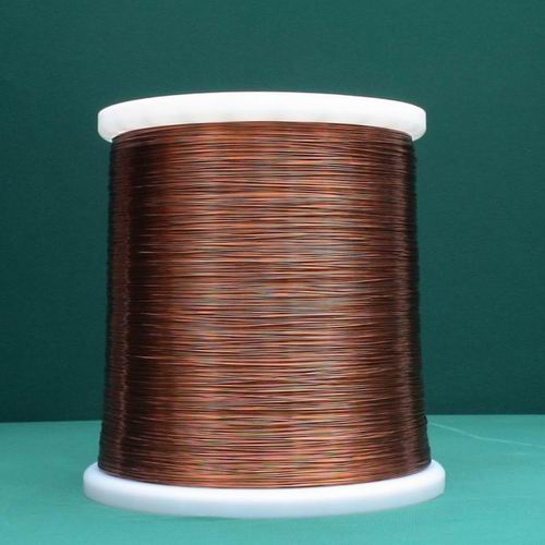
PEW-HC PEW-HC (Polyester(amide)(imide) overcoated with polyamide-imide copper magnet wire) is used to high thermal endurance, special motor , high voltage transformer electric tools, automobile electric parts, air conditioner and refrigerator compressor use in R-22 / R 134a refrigerant. Features Designation PEW-HC Thermal Class N (200℃) Structure Heat Shock 220℃ Thermoplastic Flow(Not less than ) 300℃ Feature High performance in most property Application High thermal enduranceHigh voltage transformer electric toolsSpecial motorsAutomobile electric partsAir conditionerRefrigerator compressor(used in R-22 / R134a / R407c /R410a) Specifications ‧Thermal class : N (200℃)‧Wire diameter : 0.05 ~ 3.60 mm ‧Applicable standards : CNS C2171 NEMA MW 35-C / 73-C UL Recognized(PEW-HC) IEC 317-13‧Plastic Bobbin Diameter: Symbol Capacity (kg) PL-3G 0.3 PL-5G 0.5 P-3 3 PT-1 1.5 PT-2 2 PT-4 4 PT-10 10 PT-15 15 PT-18 18 PT-25 25 PT-60 60 PT-90 90 PT-190 190 PT-270 270 ‧JIS Specification of Magnet copper wire Conductor Class 0 Class 1 Max. conductorresistance(W / km 20℃) Diameter(mm) Tolerance(mm) Min. film thickness(mm) Max. overall diameter(mm) Min. film thickness(mm) Max. overall diameter(mm) 0.100.110.120.130.14 ±0.008±0.008±0.008±0.008±0.008 0.0160.0160.0170.0170.017 0.1560.1660.1800.1900.200 0.0090.0090.0100.0100.010 0.1400.1500.1620.1720.182 2647.0002153.0001786.0001505.0001286.000 0.150.160.170.180.19 ±0.008±0.008±0.008±0.008±0.008 0.0170.0180.0180.0190.019 0.2100.2220.2320.2460.256 0.010.0.0110.0110.0120.012 0.1920.2040.2140.2260.236 1111.000969.500853.500757.200676.200 0.200.210.220.230.24 ±0.008±0.008±0.008±0.008±0.008 0.0190.0190.0190.0200.020 0.2660.2760.2860.2980.308 0.0120.0120.0120.0130.013 0.2460.2560.2660.2780.288 607.600549.000498.400454.500416.200 0.250.260.270.280.29 ±0.008±0.010±0.010±0.010±0.010 0.0200.0200.0200.0200.020 0.3180.3300.3400.3500.360 0.0130.0130.0130.0130.013 0.2980.3100.3200.3300.340 382.500358.400331.400307.300285.700 0.300.320.350.370.40 ±0.010±0.010±0.010±0.010±0.010 0.0210.0210.0210.0220.023 0.3740.3940.4240.4460.480 0.0140.0140.0140.0140.015 0.3520.3720.4020.4240.456 262.900230.000191.200170.600145.300 0.450.500.550.600.65 ±0.010±0.010±0.020±0.020±0.020 0.0240.0250.0250.0260.027 0.5320.5860.6460.6980.752 0.0160.0170.0170.0170.018 0.5080.5600.6200.6720.724 114.20091.43078.15065.26055.310 0.700.750.800.850.90 ±0.020±0.020±0.020±0.020±0.020 0.0280.0300.0310.0320.033 0.8040.8600.9140.9661.020 0.0190.0200.0210.0220.023 0.7760.8300.8820.9340.986 47.47041.19036.08031.87028.350 0.951.001.101.201.30 ±0.020±0.030±0.030±0.030±0.030 0.0340.0360.0370.0370.039 1.0721.1381.2421.3421.448 0.0240.0250.0260.0260.027 1.0381.1021.2041.3041.408 25.38023.33019.17016.04013.610 1.401.501.601.701.80 ±0.030±0.030±0.030±0.030±0.030 0.0390.0410.0410.0420.042 1.5481.6541.7541.8561.956 0.0270.0280.0280.0290.029 1.5081.6121.7121.8141.914 11.70010.1608.9067.8717.007 1.902.002.102.202.30 ±0.030±0.030±0.030±0.030±0.030 0.0440.0440.0450.0460.046 2.0622.1622.2662.3682.468 0.0300.0300.0310.0320.032 2.0182.1182.2202.3222.422 6.2785.6565.1234.6624.260 2.402.502.602.702.80 ±0.030±0.030±0.030±0.030±0.030 0.04800490.0490.0490.049 2.5742.6782.7782.8782.978 0.0330.0340.0340.0340.034 2.5262.6282.7282.8282.928 3.9083.5983.3243.0792.861 2.903.003.203.403.60 ±0.030±0.030±0.040±0.040±0.040 0.0490.0490.0490.0490.049 3.0783.1783.3883.5983.808 0.0340.0340.0340.0340.034 3.0283.1283.3383.5483.758 2.6652.4892.1981.9451.732 Conductor Class 2 Max. conductor resistance(W / km 20℃) Diameter(mm) Tolerance(mm) Min. film thickness(mm) Max. overall diameter(mm) 0.050.060.07 ±0.003±0.003±0.003 0.0040.0040.004 0.0690.0810.091 10,240.006,966.004,990.00 0.080.090.100.110.12 ±0.003±0.003±0.003±0.003±0.003 0.0050.0050.0050.0050.006 0.1030.1130.1250.1350.147 3,778.002,959.002,381.001,957.001,636.00 0.130.140.150.160.17 ±0.003±0.003±0.003±0.003±0.003 0.0060.0060.0060.0070.007 0.1570.1670.1770.1890.199 1,389.001,193.001,037.00908.80803.20 0.180.190.200.210.22 ±0.003±0.003±0.003±0.003±0.004 0.0080.0080.0080.0080.008 0.2110.2210.2310.2410.252 715.00640.60577.20522.80480.10 0.230.240.250.260.27 ±0.004±0.004±0.004±0.004±0.004 0.0090.0090.0090.0090.009 0.2640.2740.2840.2940.304 438.10402.20370.20341.80316.60 0.280.290.300.320.35 ±0.004±0.004±0.005±0.005±0.005 0.0090.0090.0100.0100.010 0.3140.3240.3370.3570.387 294.10273.90254.00222.80185.70 0.370.400.450.500.55 ±0.005±0.005±0.006±0.006±0.006 0.0100.0110.0110.0120.012 0.4070.4390.4900.5420.592 165.90141.70112.1089.9574.18 0.600.650.700.750.80 ±0.008±0.008±0.008±0.008±0.010 0.0120.0120.0130.0140.015 0.6440.6940.7460.7980.852 62.6453.2645.8439.8735.17 0.850.900.951.00 ±0.010±0.010±0.010±0.012 0.0150.0160.0170.017 0.9040.9561.0081.062 31.1127.7124.8422.49 ‧NEMA Specification of Magnet copper wire AWGSIZE Nom.Diameter (mm) Single Build Heavy Build Min. film thickness(mm) Max. overall diameter(mm) Min. film thickness(mm) Max. overall diameter(mm) 44 0.051 0.0025 0.061 0.005 0.069 43 0.056 0.0025 0.066 0.005 0.074 42 0.064 0.0025 0.076 0.0065 0.084 41 0.071 0.004 0.086 0.0065 0.091 40 0.079 0.004 0.094 0.0065 0.102 39 0.089 0.004 0.104 0.0075 0.114 38 0.102 0.004 0.119 0.009 0.130 37 0.114 0.005 0.135 0.009 0.145 36 0.127 0.005 0.147 0.010 0.160 35 0.142 0.005 0.163 0.0115 0.178 34 0.160 0.0065 0.183 0.0115 0.198 33 0.180 0.0065 0.206 0.0125 0.224 32 0.203 0.0075 0.231 0.014 0.249 31 0.226 0.0075 0.254 0.015 0.274 30 0.254 0.009 0.284 0.0165 0.302 29 0.287 0.009 0.320 0.019 0.338 28 0.32 0.010 0.356 0.0205 0.373 27 0.361 0.010 0.396 0.0205 0.419 26 0.404 0.012 0.439 0.0215 0.462 25 0.455 0.0115 0.493 0.023 0.516 24 0.511 0.0125 0.551 0.024 0.577 23 0.574 0.0125 0.617 0.0255 0.643 22 0.643 0.014 0.686 0.0265 0.714 21 0.724 0.014 0.770 0.028 0.800 20 0.813 0.015 0.864 0.0305 0.892 19 0.912 0.015 0.963 0.032 0.993 18 1.024 0.0165 1.077 0.033 1.110 17 1.151 0.018 1.207 0.0355 1.240 16 1.29 0.018 1.349 0.037 1.384 15 1.45 0.019 1.509 0.038 1.549 14 1.628 0.0205 1.692 0.0405 1.732 13 1.829 0.0205 1.892 0.0405 1.934 12 2.052 0.0205 2.117 0.0405 2.163 11 2.304 0.0215 2.373 0.042 2.418 10 2.588 0.0215 2.660 0.043 2.703 9 2.906 0.0215 2.980 0.043 3.023 8 3.264 0.0215 3.338 0.0445 3.383

PEW-H PEW-H (Polyester(amide)(imide) copper magnet wire) is used to special motor high voltage transformer generator and electric tools. Features Designation PEW-H PEW-H+ Thermal Class H (180℃) N (200℃) Structure Heat Shock 200℃ 220℃ Thermoplastic Flow(Not less than ) 300℃ 300℃ Feature 1.Good electrical property 2.Chemicals and heat endurance 3.Good mechanical property Application Special motorHigh voltage transformer generatorElectric tools Specifications ‧Thermal class : H (180℃), N (200℃)‧Wire diameter : 0.05 ~ 3.60 mm ‧Applicable standards : CNS C2169 JIS-C3202-8 NEMA MW 30-C (H class) IEC 317-8 NEMA MW 74-C(N class)‧Plastic Bobbin Diameter: Symbol Capacity (kg) PL-3G 0.3 PL-5G 0.5 P-3 3 PT-1 1.5 PT-2 2 PT-4 4 PT-10 10 PT-15 15 PT-18 18 PT-25 25 PT-60 60 PT-90 90 PT-190 190 PT-270 270 ‧JIS Specification of Magnet copper wire Conductor Class 0 Class 1 Max. conductorresistance(W / km 20℃) Diameter(mm) Tolerance(mm) Min. film thickness(mm) Max. overall diameter(mm) Min. film thickness(mm) Max. overall diameter(mm) 0.100.110.120.130.14 ±0.008±0.008±0.008±0.008±0.008 0.0160.0160.0170.0170.017 0.1560.1660.1800.1900.200 0.0090.0090.0100.0100.010 0.1400.1500.1620.1720.182 2647.0002153.0001786.0001505.0001286.000 0.150.160.170.180.19 ±0.008±0.008±0.008±0.008±0.008 0.0170.0180.0180.0190.019 0.2100.2220.2320.2460.256 0.010.0.0110.0110.0120.012 0.1920.2040.2140.2260.236 1111.000969.500853.500757.200676.200 0.200.210.220.230.24 ±0.008±0.008±0.008±0.008±0.008 0.0190.0190.0190.0200.020 0.2660.2760.2860.2980.308 0.0120.0120.0120.0130.013 0.2460.2560.2660.2780.288 607.600549.000498.400454.500416.200 0.250.260.270.280.29 ±0.008±0.010±0.010±0.010±0.010 0.0200.0200.0200.0200.020 0.3180.3300.3400.3500.360 0.0130.0130.0130.0130.013 0.2980.3100.3200.3300.340 382.500358.400331.400307.300285.700 0.300.320.350.370.40 ±0.010±0.010±0.010±0.010±0.010 0.0210.0210.0210.0220.023 0.3740.3940.4240.4460.480 0.0140.0140.0140.0140.015 0.3520.3720.4020.4240.456 262.900230.000191.200170.600145.300 0.450.500.550.600.65 ±0.010±0.010±0.020±0.020±0.020 0.0240.0250.0250.0260.027 0.5320.5860.6460.6980.752 0.0160.0170.0170.0170.018 0.5080.5600.6200.6720.724 114.20091.43078.15065.26055.310 0.700.750.800.850.90 ±0.020±0.020±0.020±0.020±0.020 0.0280.0300.0310.0320.033 0.8040.8600.9140.9661.020 0.0190.0200.0210.0220.023 0.7760.8300.8820.9340.986 47.47041.19036.08031.87028.350 0.951.001.101.201.30 ±0.020±0.030±0.030±0.030±0.030 0.0340.0360.0370.0370.039 1.0721.1381.2421.3421.448 0.0240.0250.0260.0260.027 1.0381.1021.2041.3041.408 25.38023.33019.17016.04013.610 1.401.501.601.701.80 ±0.030±0.030±0.030±0.030±0.030 0.0390.0410.0410.0420.042 1.5481.6541.7541.8561.956 0.0270.0280.0280.0290.029 1.5081.6121.7121.8141.914 11.70010.1608.9067.8717.007 1.902.002.102.202.30 ±0.030±0.030±0.030±0.030±0.030 0.0440.0440.0450.0460.046 2.0622.1622.2662.3682.468 0.0300.0300.0310.0320.032 2.0182.1182.2202.3222.422 6.2785.6565.1234.6624.260 2.402.502.602.702.80 ±0.030±0.030±0.030±0.030±0.030 0.04800490.0490.0490.049 2.5742.6782.7782.8782.978 0.0330.0340.0340.0340.034 2.5262.6282.7282.8282.928 3.9083.5983.3243.0792.861 2.903.003.203.403.60 ±0.030±0.030±0.040±0.040±0.040 0.0490.0490.0490.0490.049 3.0783.1783.3883.5983.808 0.0340.0340.0340.0340.034 3.0283.1283.3383.5483.758 2.6652.4892.1981.9451.732 Conductor Class 2 Max. conductor resistance(W / km 20℃) Diameter(mm) Tolerance(mm) Min. film thickness(mm) Max. overall diameter(mm) 0.050.060.07 ±0.003±0.003±0.003 0.0040.0040.004 0.0690.0810.091 10,240.006,966.004,990.00 0.080.090.100.110.12 ±0.003±0.003±0.003±0.003±0.003 0.0050.0050.0050.0050.006 0.1030.1130.1250.1350.147 3,778.002,959.002,381.001,957.001,636.00 0.130.140.150.160.17 ±0.003±0.003±0.003±0.003±0.003 0.0060.0060.0060.0070.007 0.1570.1670.1770.1890.199 1,389.001,193.001,037.00908.80803.20 0.180.190.200.210.22 ±0.003±0.003±0.003±0.003±0.004 0.0080.0080.0080.0080.008 0.2110.2210.2310.2410.252 715.00640.60577.20522.80480.10 0.230.240.250.260.27 ±0.004±0.004±0.004±0.004±0.004 0.0090.0090.0090.0090.009 0.2640.2740.2840.2940.304 438.10402.20370.20341.80316.60 0.280.290.300.320.35 ±0.004±0.004±0.005±0.005±0.005 0.0090.0090.0100.0100.010 0.3140.3240.3370.3570.387 294.10273.90254.00222.80185.70 0.370.400.450.500.55 ±0.005±0.005±0.006±0.006±0.006 0.0100.0110.0110.0120.012 0.4070.4390.4900.5420.592 165.90141.70112.1089.9574.18 0.600.650.700.750.80 ±0.008±0.008±0.008±0.008±0.010 0.0120.0120.0130.0140.015 0.6440.6940.7460.7980.852 62.6453.2645.8439.8735.17 0.850.900.951.00 ±0.010±0.010±0.010±0.012 0.0150.0160.0170.017 0.9040.9561.0081.062 31.1127.7124.8422.49 ‧NEMA Specification of Magnet copper wire AWGSIZE Nom.Diameter (mm) Single Build Heavy Build Min. film thickness(mm) Max. overall diameter(mm) Min. film thickness(mm) Max. overall diameter(mm) 44 0.051 0.0025 0.061 0.005 0.069 43 0.056 0.0025 0.066 0.005 0.074 42 0.064 0.0025 0.076 0.0065 0.084 41 0.071 0.004 0.086 0.0065 0.091 40 0.079 0.004 0.094 0.0065 0.102 39 0.089 0.004 0.104 0.0075 0.114 38 0.102 0.004 0.119 0.009 0.130 37 0.114 0.005 0.135 0.009 0.145 36 0.127 0.005 0.147 0.010 0.160 35 0.142 0.005 0.163 0.0115 0.178 34 0.160 0.0065 0.183 0.0115 0.198 33 0.180 0.0065 0.206 0.0125 0.224 32 0.203 0.0075 0.231 0.014 0.249 31 0.226 0.0075 0.254 0.015 0.274 30 0.254 0.009 0.284 0.0165 0.302 29 0.287 0.009 0.320 0.019 0.338 28 0.32 0.010 0.356 0.0205 0.373 27 0.361 0.010 0.396 0.0205 0.419 26 0.404 0.012 0.439 0.0215 0.462 25 0.455 0.0115 0.493 0.023 0.516 24 0.511 0.0125 0.551 0.024 0.577 23 0.574 0.0125 0.617 0.0255 0.643 22 0.643 0.014 0.686 0.0265 0.714 21 0.724 0.014 0.770 0.028 0.800 20 0.813 0.015 0.864 0.0305 0.892 19 0.912 0.015 0.963 0.032 0.993 18 1.024 0.0165 1.077 0.033 1.110 17 1.151 0.018 1.207 0.0355 1.240 16 1.29 0.018 1.349 0.037 1.384 15 1.45 0.019 1.509 0.038 1.549 14 1.628 0.0205 1.692 0.0405 1.732 13 1.829 0.0205 1.892 0.0405 1.934 12 2.052 0.0205 2.117 0.0405 2.163 11 2.304 0.0215 2.373 0.042 2.418 10 2.588 0.0215 2.660 0.043 2.703 9 2.906 0.0215 2.980 0.043 3.023 8 3.264 0.0215 3.338 0.0445 3.383